On Friday 12th January 2007, a dramatic metro construction accident occurred in São Paulo, Brazil. Nearly the whole of one of the station caverns of 40m length suddenly collapsed, immediately followed by collapse of nearly half of the adjacent 40m diameter and 35m deep station shaft. Seven people lost their lives in the collapse.
These station and shaft constructions are close to the Pinheiros River, in the SW sector of the city, and are part of the new Line 4 (Yellow Line) of the presently expanding São Paulo Metro. The consortium CVA, Consorcio Via Amarela, composed of most of the major contractors in Brazil, were awarded the detailed design and construction of Line 4 in 2004.
The accident occurred so rapidly that there was no time for warning to be given. It is probable that suction, caused by the rapid fall of a huge undetected ridge of jointed, foliated and often deeply weathered rock weighing some 15,000 to 20,000 tons, causing an air blast in the running tunnel, actually sucked the seven Rua Capri victims to a lower level in the debris than they would have fallen if materials had been more uniform. Five of the victims were in a small bus, others were pedestrians in Rua Capri.
Boreholes for site investigation
Prior to final design and construction of the 18m span station cavern, numerous boreholes had been drilled through the soil, saprolite and weathered Pre-Cambrian gneiss. There were eleven boreholes drilled around the shaft and eastern station cavern. The four boreholes located close to the sides of the cavern, and one almost in the centre of the cavern, had indicated some zones of deeply weathered rock, especially in the biotite gneiss. Foliation was mostly steeply dipping to vertical.
The arch of the Pinheiros station was at a mean elevation of 703m. Borehole 8704 drilled near the centre of the cavern, had correctly indicated a (local) top-of-rock elevation of 706m. This was exactly the same as the mean rock elevation found in the four other closest holes.
Undetected sub-surface ridge
The tragic contrast between interpretation and reality, following 1-year of excavation through 30m of the collapsed soil, saprolite and jointed and foliated gneiss, is indicated in simplified diagrammatic form in Figure 1.
Two central ridges of less weathered rock with sloping sides provided the ‘geometry’ for potential failure. However, final collapse is believed to have been triggered by water pressure and clay-softening caused by leakage from a cracked pipe, which crossed a major discontinuity at the rear of the slide.
Rock logging and pre-grouting
During construction of the eastern station cavern, geologists had registered an increasing volume of medium quality Class III rock (RMR = 44-48) in the centre of the cavern in the direction of Rua Capri. The Class III ‘core’ was surrounded by poorer quality Class IV rock (RMR= 34-36) on either side (figure 3). That this better quality rock ‘core’ could be a threat to cavern stability was not of course imagined, until with the benefit of hindsight following the collapse, the possibility of differential weathering was considered, since a high ridge of rock was now indicated, in contradiction to earlier borehole evidence. Independent Q-logging of the five closest boreholes subsequently showed a range of Q= 0.1-4, similar to earlier logging by IPT for São Paulo Metrô, and similar to the contractor’s RMR-logging within the cavern.
Station arch primary support
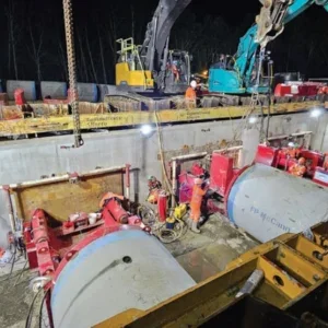
Normally the process of arching, as with a high quality rock mass, results in the need for the designed support to bear just a small fraction of the overlying load of rock. A conservative primary structural support was used to maintain stability as the cavern arch was excavated. The lattice girders had close spacing (0.85m c/c) and were embedded in a minimum thickness of 35cm of steel-fibre-reinforced sprayed concrete.
Because of the weaker rock at the sides of the cavern, conservative assumptions were made for the foundation strength and stiffness of the rock beneath the footings of the lattice girders supporting the top heading. The so-called ‘elephant feet’ supporting the structural arch, were placed in large excavated recesses in the rock, at either side of the cavern.
CVA excavated with small drill-and-blast advances and applied the successive structural support elements up to the face, followed by shotcreting. An earlier Basic Design lattice girder spacing of 1.25m c/c was rejected because of the loads resulting from the assumed inadequate rock cover, as the desirable arching in the rock above the cavern was expected to be much reduced.
A lighter, cheaper primary support alternative for the cavern, consisting of rock bolt reinforcement of the rock arch, and significantly less sprayed concrete thickness was rejected, since the five closest boreholes had indicated a mean top-of-rock elevation of 706m, only 3m above the cavern arch roof. This was considered insufficient for conventional support with rock bolts, since this rock was also deeply weathered in various locations, with UCS expected to be 5 to10MPa, sometimes even less than this.
Final support of this large multiple-component station structure was to have consisted of steel-reinforced concrete. However this stage of construction had not been reached at the time of collapse, either in the eastern or western station caverns, or in the central station shaft. A first 4m high bench to elevation 693m was completed, prior to accelerated deformation in the last three days before the collapse. This abruptly followed several months of gently increasing, then stable maxima along the cavern, ranging from 14 to 24mm.
Likely collapse mechanisms
During most of 2007 and in the first 3 months of 2008, the fallen rock sketched in Figure 2 was carefully excavated, under the supervision of a government institute IPT, working on behalf of the Police. This post-collapse excavation was performed from the base of an increasingly deep open excavation supported eventually by hundreds of tie-backs. It will eventually be completed as a cut-and-cover station platform construction.
Differential weathering along the sides of the 10 to 13m high ridge of rock was identified during this post-collapse excavation. At some distance above the cavern arch, this unidentified wedge-shaped ridge had developed into a threat to stability, due to its adversely sloping clay or soil-filled boundaries which hindered arching, and instead stood ready to supply a huge load onto the lattice girders and steel-fibre reinforced shotcrete support.
Figure 4 shows conceptual drawings of what is believed to have caused the failure of the cavern: a jointed and variously weathered ‘ridge-of-rock’ structure, that must have had its origin in differential weathering between what, at cavern level had been class III rock (the ‘core’) surrounded by the poorer class IV rock which presumably weathered more easily as the surface was approached.
Mechanism seen in the support
The collapsed parts of the cavern’s structural support were reached by February 2008, at elevations of 693 to 695m, immediately above the original cavern floor level of 693m. The cavern had been excavated to a height of 10m when the collapse occurred. A final bench had remained to be excavated below this level, in mostly sound rock.
Evidence for extreme over-loading of the structural support, causing its immediate collapse was eventually exposed near the base of the excavations, which continued through March 2008, more than 14 months after the collapse. In part of the cavern there was evidence of footing failure, meaning fracturing of the rock beneath the ‘elephant-footings’, followed by folding and inwards displacement of wall shotcrete and mesh.
There was however, more extensive evidence of extraordinary ‘punch-loading’ of the heavy arch support, with multiply folded layers of structural support, and even of lattice girder steel failed in tension. This is evidence of extremely unusual, and probably high-velocity loading levels.
Computer modelling
The likely mechanisms of failure of the support could be partially demonstrated in post-collapse discontinuum (jointed rock mass) modelling, and in stress fracture modelling of the over-loaded ‘elephant footings’. These models were performed by Dr. Baotang Shen (FRACOD) and by Dr. Stavros Bandis (UDEC). The FRACOD model showed cracked foundations beneath the ‘elephant-footings’, when realistic levels of rock strength, fracture toughness, and exceptional rock ridge loadings of up to 20,000 tons were modelled. There was no cracking in any of the three cases (UCS = 5, 10 or 15MPa) when load levels were low, as reasonably expected in the design. The UDEC model showed a final stage of cavern collapse in progress, as the wedge-shaped-ridge of rock begins to fall. This code was not used in design studies due to the limits of investigation by small-diameter drillcore.
Adverse features
A collapse of this magnitude, occurring with a speed sufficient to cause an air-blast that blew over a distant fleeing tunnel worker, obviously required other adverse features for it to occur at this location. There were by chance three additional adverse features exactly beneath Rua Capri. Taken alone these additional factors would not have been a threat to stability, but in unexpected combination they caused one of the largest urban civil engineering tunnelling accidents on record. The triggering mechanism for this loading to be released proved to be totally unexpected.
Geological faults or major discontinuities crossing tunnels or caverns occur so frequently that the tunnelling industry developed standard support measures long ago. In the case of Pinheiros, a smooth major discontinuity crossed the cavern at a steep and nearly perpendicular angle. This is most favourable in normal circumstances. At cavern level 20m below, this feature did not distinguish itself from the smooth, planar rock joint (fracture) set that consistently crossed the cavern at the same steeply-dipping angle. The standard heavy support was continued to the eastern end of the cavern. In this end of the cavern, beyond the major discontinuity, no collapse occurred.
The unpredictable event that probably triggered the massive instantaneous failure along the multiple adverse rock structures lying undetected above the cavern is believed to be the cracking of a 30 years-old 700mm diameter sewage and storm water pipe that crossed the same discontinuity exactly beneath Rua Capri. Compounding the situation was the fact that this potential artificial water supply was located immediately following a change of cross section of the pipe, from 1000mm to 700mm. This represents a 50% reduction in flow area, which probably caused an elevated water pressure and unwanted water supply in just the wrong locations.
Naturally there had never been a cavern under this discontinuity marking the eastern boundary of the collapse. It is surmised that there may have been some down-dip sliding deformation as a result of the approaching and passing cavern arch. This can never be prevented, and is of small millimetre-scale magnitude, but it may have allowed the water from the cracked pipe to flow more easily, transmitting pressure further into the unknown, adverse rock structures.
The artificial water supply, seen flowing from the broken pipe in a video film taken immediately after the collapse, would have helped to soften clay along the boundary discontinuity (marked FF in figure 5), and also have had the potential to soften and lubricate the weathered boundaries of local parts of the adverse wedge-shaped ridge of rock running undetected above much of the cavern arch. Reduced effective stress resulting from increased pore pressure is another possibility for accelerating the onset of failure.
The final block release surface at the other end of the largest rock ridge may have been the deeply weathered boundary between the two ‘halves’ of the ridge, in the approximate location of borehole 8704, at an original chainage of 7100m. Alternatively there could have been ‘down-stepping’ across the smooth steeply dipping cross-joints that crossed the cavern at numerous locations. The second smaller rock ridge effectively had the shaft wall as its western release surface.
A final unexpected factor that may have compounded the scale of collapse at Pinheiros, was the distant 75° to 80° dipping rear discontinuity (FF) under the eastern pavement of Rua Capri. Although nearly 40m from the shaft, the down-dip component of sliding during the 10m collapse, may have pushed both the falling ridges of rock some meters towards the side of the shaft, thereby further guaranteeing the shaft’s partial failure.
Inevitably, when an adjacent circular shaft that relies on circular and radial loading, suddenly loses a large portion of its circumference, due to collapse of the station cavern, there is insufficient stiffness in the primary lining phase to resist the uneven and dynamic load. Failure of part of the shaft is then inevitable.
Conclusions
The 2007 accident at Pinheiros focussed engineers and planners attention on risk, especially in the case of sub-urban tunnelling in São Paulo. Regrettably the high cost and physical impossibility of performing necessary but quite unreasonable levels of sub-urban site investigation could prevent the execution of many shallow city metro projects. This would be due to the socially and commercially unacceptable degrees of disturbance beneath too many roads and buildings. Deeper construction from the underground, as practiced of necessity in many cities lacking suitable geology, could be a future solution, as rock conditions for tunnelling are fundamentally more favourable at depth, whereas the ‘near-surface’ is more unpredictable due to deep weathering in such tropical regions. T&T
Fig 1 – Top) Sketch of the anticipated top-of-rock elevations based on the five nearest boreholes, including one hole near the centre of the cavern. Bottom) Sketch of the extraordinary reality, in over-simplified form Fig 1 Fig 2 – The undetected ridges of rock (1, 2) missed due to the location of hole 8704 Fig 2 Fig 3 – Longitudinal sections showing progressing number of lattice girders at two of the mapped cavern faces. The RMR rock class values of the ‘core’ (B) and the surrounding rock (A) are listed. Pre-injection screens (enfilagens) were suspended afterFig 3 Fig 4 – Conceptual model that was developed as a possible explanation of the final stage of differential weathering, leaving a ridge (and wedge) of rock that threatened stability as it prevented efficient arching above the cavern due to clay along its sidFig 4 Fig 5 – The fractured pipe, with the change of cross-section and possible raised water pressure occurring in just the wrong location. Rua Capri pavement is at ch 7120m Fig 5 The Pinheiros station cavern and shaft collapse of 12th January 2007 The Pinheiros station cavern A view of the heavy primary support in the top heading of the eastern station cavern. Lattice girders were at 0.85m c/c spacing, embedded in at least 35cm thickness of steel fibre-reinforced shotcrete
Heavy primary support View of the cavern (and running tunnel) some days prior to collapse Cavern and running tunnel Assessing the damage following the collapse, notice the bent lattice girders Assessing the damage Evidence for ‘elephant-footing’ failure Evidence for ‘elephant-footing’ failure Shear deformation on this major discontinuity when the cavern approached and passed below, may already have fractured this 700mm pipe Shear deformation FRACOD modelling of rock fracturing caused by over-stressing of the lattice girders in the cavern arch, caused by the unknown elevated ridge of rock FRACOD modelling of rock fracturing Final stage of collapse in a UDEC model of the lattice-girder and S(fr) supported cavern, following softening of plastic hinges in the arch. Footing failures with local jointing were also modelled Final stage of collapse