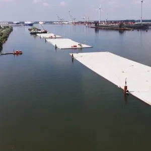
Rome’s Metro Line C is among the most significant and challenging infrastructure projects underway in the world today. Running through the heart of the city the project faces both logistical and historical challenges that are inevitable when building a critical piece of infrastructure in one of the world’s oldest cities.
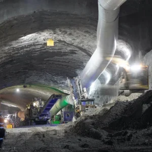
Construction of the project is being carried out under a turnkey contract. Client Roma Metropolitane has awarded the contract to the joint venture Metro C (formed of Astaldi, Vianini Lavori, Ansaldo Trasporti-Sistemi Ferroviari, Cooperativa Muratori e Braccianti di Carpi, Consorzio Cooperative Costruzioni), which has turned to the most sophisticated technology available to bore the twin 17.6km tunnels. It is using a total of four identical EPB-TBMs from Germany’s Herrenknecht.With a cutter head diameter of 6.71m and a 10.7m shield length, the EPB machines are capable of cutting under the city at 88mm/min.
As far as the tunnel lining is concerned, it consists of precast reinforced concrete segments of a thickness of 300mm, internal diameter of 5.8m, external diameter 6.4m. Each prefabricated ring is 1.4m long and has six main segments with a key. The rings are of universal double tapered type and fit 19 possible different positions depending on the radius of curvature to be obtained. Segments are cast in a prefabrication plant by using a fixed formwork installation for concrete steam curing.
To date the bore itself has gone very well. The boring machines have already obtained excellent production rates, with an excavation length of approximately 10km over slightly more than one year of activity. They have also obtained satisfying results in terms of compliance with excavation parameters and measured surface settlement values.
Hydraulic seal equipment
TBM S-409, the first of the four tunnel boring machines to begin excavation activities, completed the section St. Torrenova – Shaft 5.4 (even-numbered track) on 3 October 2009. For breakthrough into the reception shaft (5.4) a metal ring system with hydraulic seal was used, allowing the TBM to bore through the wall with groundwater behind it. This technique was subsequently adopted for the second TBM – S-410, which reached the reception shaft on 25 October 2009, thus completing the same section along the odd-numbered track. This method was used as an alternative to tunnel-end grouting, and allows tunnellers to carry out either the launch phase and/or the run-out phase from a shaft or station, through a system of seals waterproofing the area around the TBM’s shield to prevent possible water seepage from behind the walls.
For this reason it is worth underlining that the fourth and final TBM in operation, TBM S-479, will soon adopt that same system but not for final breakthrough into a shaft. Instead it will be used for restarting the bore after crossing the Teano Station. Were this equipment not available, a more common approach would be to use jet-grouted concrete blocks behind the shaft or station wall eye for a length exceeding the shield length so that, when the last wall is crossed through, the TBM shield has already bored one or two rings erected within the block itself, thus ensuring a water seal.
This is the first time in Italy that hydraulic seal technology for an EPB’s reception phase has been used within a shaft. The reception (or run-out) phase is much more complex than the start phase, mainly due to the high-precision topographical guidance required for the TBM. It must be ensured that, when going through the metal ring, the shield’s position has the lowest possible plano-altimetric deviation with respect to design. In fact, seal centering may be adjusted by means of hydraulic jacks, the maximum extension of which must not exceed 100mm along its radius. Another reason that the reception phase is more complex than launch is due to the pressure balance. After breaking through the wall, and up to going through the seal, the pressure of possible water flows, which may occur around the shield because of the void between soil and the shaft chamber, must be counter-balanced.
The equipment required for the hydraulic seal was manufactured by MSDHerrenknecht, and consists of the following elements. Firstly a ring with radial pins (concrete shuttering pipe) is buried into a reinforced concrete template that is normally cast in situ close to the wall softeye (in this case, the concrete was previously cut to form the hole). This is a disposable element that will remain embedded into the concrete template.
The next element is a ring with two seals that is bolted to the concrete shuttering pipe. These two seals have two independent compressed-air circuits, ensuring a design maximum operating pressure of 7 bar. Such a ring may be adjusted, up to a maximum of 100mm along its radius, by means of hydraulic jacks. The metal structure is entirely reclaimable to be used in other projects with the same dimensions and characteristics.
The equipment also requires a temporary cover to balance groundwater pressure due to excavation face progress before pressure is exerted on the seals. The cover is bolted to the ring with a seal. Figure 1 shows the exploded layout before assembly.
Geological and geotechnical aspects
From a geological perspective the ground to be driven through is essentially pyroclastic soils making up part of Latium’s volcanic complex. The overburden above tunnel top ranges from a minimum of 6m up to a maximum of 24m. Groundwater load along the tunnel path is subject to changes but is present throughout the entire tunnel, apart from a section at one end, on the side of Torrenova Station. In the area where the tunnel intersects the shaft, groundwater head above the tunnel top is of approximately 9m.
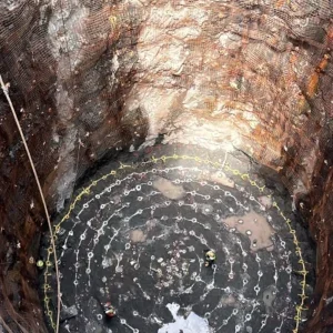
Characteristics of the reception shaft (run-out shaft)
The round shape of the reception shaft required the construction of a reinforced concrete structure to anchor the equipment to the shaft wall. Moreover, the shaft’s considerable depth and small diameter— which was necessary due to potential conflicts with surrounding pre-existent structures, and increased operational difficulties of installation with the equipment—deserve particular attention, as does the run-out and subsequent
disassembly of the TBM. The shaft’s walls were preliminarily cut at the position of intersection with the TBM, taking advantage of a jet-grouted zone, of length approximately 4m, consisting of plastic piles enclosed within concrete perimeter walls (Figure 2).
A similar procedure will be adopted, within the twin shaft, for the breakthrough of the second TBM carrying out excavation along the same direction and, in the future, also for the other two TBMs excavating toward the opposite direction.
Operational method adopted for TBM breakthrough
The breakthrough operations by using the metal ring requires the preparation of a detailed sequence of construction phases starting from the most recent excavation progress (approach to the last wall to be crossed through) and until the shield has gone through the seals and pressure is exerted on the latter.
a) Assembly of the equipment elements in the run-out shaft.
b) Progress of TBM excavation under earth-pressure balance mode until the shield runs into the grouted zone.
c) Progressive reduction in pressure supporting the excavation face during the last meters of excavation and until breaking through the last diaphragm. During this phase, the backfill is carried out in nonconsolidated soil and, therefore, there is still the possibility of water inrushes between the shield tail and the excavation face.
d) Breakthrough and void crossing (for approximately 5m, corresponding to three to four progress steps) toward seals, while still keeping the cover closed. During this phase, several supplementary activities have to be carried out including disassembly of peripheral tools, which might damage the seal; removal of muck accumulated in front of cutting head consequently to the breakthrough; removal of provisional protections from the seal in the invert area; topographic verification of the actual position of the cutting head with respect to the metal ring.
e) Cutting head goes through the seal and places pressure on it.
f) Removal of the closing cover and subsequent transit of TBM shield up to reaching disassembly position. During this phase, particular attention must be devoted to segment backfill during the excavation progress until reaching the grouted body so as to waterproof the area between the shield and the tail of the TBM.
Advantages and critical aspects for future consideration
The use of the equipment offers some important advantages the most significant of which is control of water inrushes. However there is an intermediate phase, between the breakthrough and pressurization of the seal, during which it is necessary to balance possible water inrushes from the hollow space between the shield and the soil. Another advantage is that it offers a reduction in soil consolidation from the surface. In the case of shafts or stations, to be crossed through as open zoes, in urban environments where accessible areas required for consolidation grouting may be considerably limited, the exploitation of such technology contributes to a significant reduction in the dimensions of grouted zone. In addition the equipment installed is entirely reusable in subsequent projects (apart from the shuttering pipe buried into the concrete template), which makes it possible to compare this solution with a grouted body from the economic point of view.
The experiences of the project team did however raise some critical aspects which, in our opinion, should be addressed in order to improve the efficiency and effectiveness of the method. Breakthrough debris is drawn through by the cutting head and may be removed, theoretically, only after pressure is exerted on the seal and the cover is opened. This gives rise to the following two drawbacks: the risk of damaging the seal because of contact with the debris (which is sometimes of considerable size) and the absence, between the seal and the cover, of hollow space sufficient to contain the quantity of debris accumulated and drawn by the cutting head. All the above makes it necessary to carry out very exacting operations in a hyperbaric environment; such operations mainly consisting in crushing and removing said excavation debris before making the shield go through the seal.
The cover is also equipped with water discharge outlets which are easily clogged by soil and mud debris and are made unserviceable in a very short time. This makes it impossible to remove, in a controlled manner, the water between the cover and excavation chamber, and to assess the consequent stabilisation of groundwater level, also with possible hyperbaric operations to be carried out. Increasing the number of water outlets and arranging the same more uniformly on the cover surface would improve the equipment serviceability.
Finally there is a need to remove peripheral tools before making the shield go through the seal which makes hyperbaric operations unavoidable, although such operations are of a limited duration and, therefore, are not considered as critical.
Table 1 – The capabilities of the Four EPB-TBMs from Herrenknecht The concrete shuttering pipe ring with radial pins The 2-seal ring can be reused in other projects of the same dimension and characteristics A temporary cover is required to balance groundwater pressure The cover is bolted to the ring. Figure 1 – A breakdown of the equipment required for the hydraulic seal Figure 2 – The TBM encountered reinforced concrete before the shaft The TBM’s cap and the 2-seal ring as it enters the shaft Working in the heart of Rome provided logistical challenges with its historic streets Once the cover is removed, particular attention must be paid to make sure the area between the shield and the tail of the TBM is waterproofed