INTRODUCTION
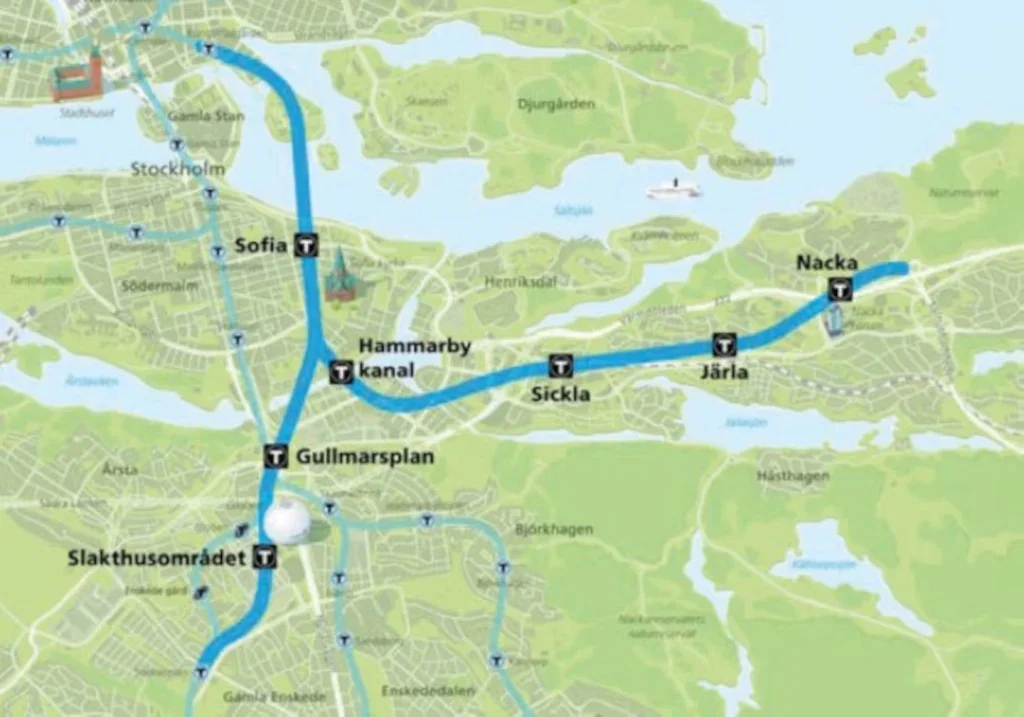
The Stockholm Metro Blue Line is being extended southwards and eastwards, starting from the monumental Kungsträdgården station, descending as steep as allowed to pass underneath the Saltsjön Lake through challenging fault zones, and will in the near future connect the areas of Södermalm, Nacka and Sockenplan.
The enormous challenge was commissioned to the organisation Förvaltning för utbyggd tunnelbana (FUT), a transport agency for local authority Region Stockholm. In 2014, FUT entrusted development of the project to the Sweco-Typsa Design Joint Venture. Work began at the project’s earliest stages, starting from the conceptual design (‘Systemhandling’, in the Swedish framework) and has also included producing legal documents at the detailed design stage, undertaking tender assessment during procurement, and supporting the client during the construction stage.
Construction is ongoing in the capital and the Blue Line metro extension is expected to be in operation in 2030.
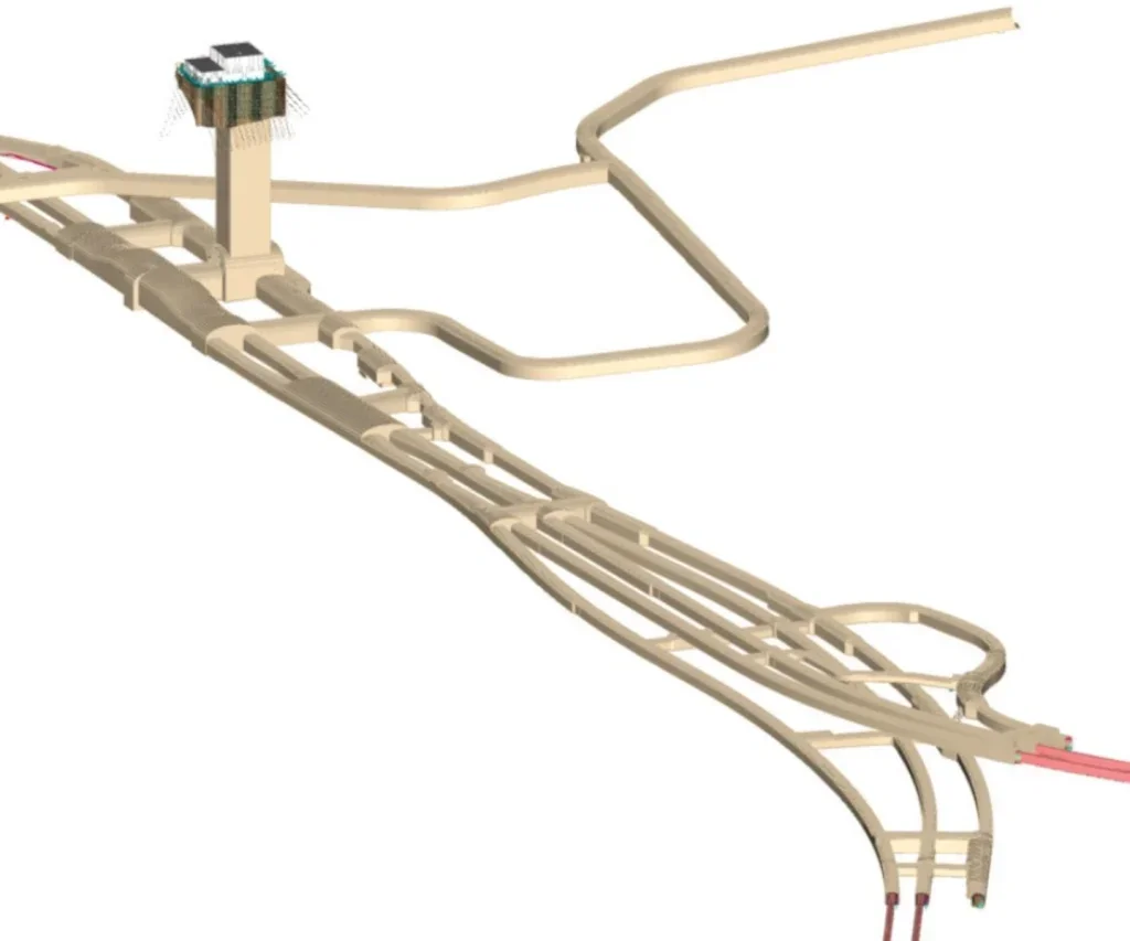
The metro line extension consists of new twin rail tunnels plus a parallel service gallery, and it splits south of Sofia station into two branch lines – one south-bound to Sockenplan and the other east-bound to Nacka C. Cross galleries connect the three parallel tunnels (twin rail plus service) at approximately 250m intervals to provide for ventilation, evacuation, and mechanical, electrical & plumbing (MEP), rail systems, and maintenance.
The passengers will access these new routes on the Blue Line metro extension through seven stations, of which six are new. Two of the new stations have the platforms at great depths (Gullmarsplan station, at 70m depth; and, Sofia station, at 100m).
A deeper alignment was selected for the new line at the preliminary stage of project development to help avoid challenging geology, such as fault zones at Saltsjön Lake or the Ladugårdslandsviken passage.
The access to conventional stations is provided through sloped galleries that include escalators, while high-capacity elevators will take passengers down vertical shafts to the deepest stations (Sofia, Gullmarsplan, and Nacka C). The shafts are excavated by Drill & Blast Method (DBM) that follow narrower pilot excavations undertaken by raise boring. Spoil from all shaft excavation – pilot and widening by DBM – is removed by gravity, the debris falling down the initial narrow conduits.
To reach the underground working areas, a total of six new access Working Tunnels have been excavated, and also an existing access tunnel used formerly to build Kungsträdgården station, in the 1970s, has been reopened. These ancillary tunnels will be used when the Blue Line extension is in service to give access to maintenance equipment and to be part of the underground layout supporting the ventilation and evacuation systems.
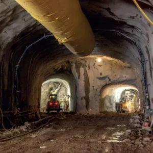
The construction process for the tunnels, caverns, galleries and shafts uses the traditional shotcrete lining, following after DBM excavation. The combination is a standard method that is widely used for Swedish infrastructure, which also includes systematic preexcavation grouting (PEG) around the perimeter of the planned excavation zones to limit the groundwater leakage and comply with allowed environmental limits.
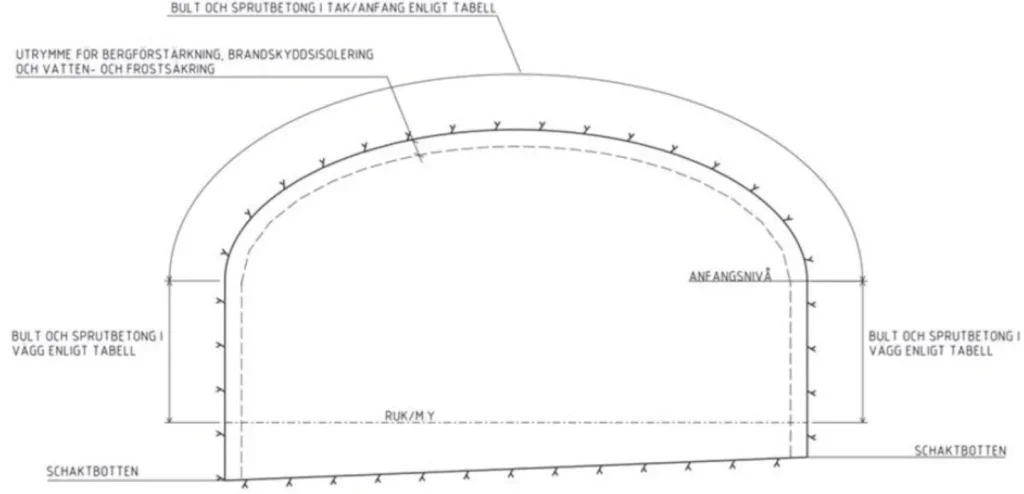
The geometry of the tunnels accommodates the natural stresses and existing rock conditions in the Scandinavian granitic batholith. This geometry has been previously tested and proven in several other large-scale tunnels and caverns. It consists of vertical sidewalls and elliptical roofs with a vault height to horizontal span ratio between 0.20 and 0.25 (see Figure 3). This geometry corresponds to the characteristic Scandinavian lowered vaults, optimising the geometry to take advantage of the existing high horizontal rock stresses.
A toolbox consisting of several rock support typical sections was provided in the design, considering different variables: span; rock quality; sidewall heights; fire classification; and, special conditions.
In general, no final lining is provided in these tunnels as per previous experience and due to the very high rock mass quality, in general. However, watertight circular concrete lining was proposed in three different zones where construction would be under challenging conditions: 1) where low rock cover is present; 2) heavily fractured rock mass; and, 3) high water pressure. These zones are the Ladugårdslandsviken passage, passing under the Saltsjön Lake, and Mårtensdal Passage.
TYPSA’S CONTRIBUTION
Typsa is a leading global consulting firm in the metropolitan railway sector and has contributed its broad international experience to this Blue Line metro extension project, helping to improve public transport in Stockholm.
The company provides a wide range of expertise to develop the preliminary and detailed design across various disciplines, including rock mechanics, structures, electromechanical and railway systems (telecommunications, signalling and third rail), architecture, civil works, environmental consulting, and vertical transportation.
Regarding the use of Building Information Modelling (BIM) on the project, Typsa was involved not only in the modelling work but also in developing the BIM Execution Plan (BEP) based on the Employer’s Information Requirements (EIR). As part of the engagement, the company also participated in important decisions such as defining the Level of Design (LoD) for the tunnel models, selecting types of geometrical entities to be modelled, management of geological and geotechnical information, and coordination with other disciplines.
In the past years, the company has invested in self-funded research programmes to explore and optimise modelling of tunnels through the most relevant commercial modeling tools. Also, Typsa’s tunnel design team in Spain has played an important role in the Working Group 22 (WG22) of the Spanish Tunneling Association (AETOS), which collaborates with the International Tunnelling and Underground Space Association (ITA-AITES).
WHAT ‘BIMERS’ WHISPER TO TUNNELLERS
The beginning of 21st Century has brought major improvements in efficiency and organisation to the building industry, thanks to computing and modelling innovations, bringing a BIM philosophy for wider application. After this success, the next targeted industry to apply these new tools and philosophy has been civil engineering, with tunnels being one of the main elements due to their specific complex conditions, costly executions, and comprehensive maintenance. And, BIM has proven to be important to the Stockholm Blue Line metro extension project.
Having the BIM tools and the experience from the building sector, all seemed to be set up and ready; what could go wrong then in modelling tunnels? Experts in BIM provided working procedures at the beginning. But specific needs for tunnel design were not properly addressed by these existing procedures, and the efficiency of available tools at that moment were insufficient for the particular requirements of underground infrastructure development.
The reason for such mismatch can be explained by the fact that tunnels are intimately connected to the surrounding ground and cannot be understood separately from it. In addition, cross sections are made of complex geometrical entities that, in general, are difficult to program for in traditional modelling software. Both aspects are less relevant in buildings (where more cartesian geometries are used), and so the applications back then were mostly focused on handling different tasks (mostly aimed to organise and distribute orthogonal volumes).
UTILISING POWER OF BIM
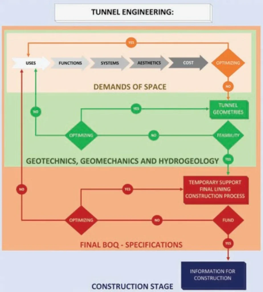
Cross sections and open volumes in tunnels and caverns are the result of arranging space demands based on functional requirements in combination with tunnel engineering requirements, following a process as the one proposed in Figure 4.
Establishing and supporting a collaborative work environment should be the philosophy in a BIM-based project. However, the hierarchy of requirements should be properly established to optimise design time, execution time, and cost. In this sense, it is important to correctly determine geotechnical requirements.
As the tunnel itself is seldom perceived by the final user of the rail service, such leadership by a tunnel engineer may be controversial. In the end, the interaction with the tunnel itself is indirect through experiencing the open space inside the tunnel with the perception of the conditions of temperature, humidity, and lighting.
Rock engineers took the lead in the Stockholm Blue Line metro extension project, which helped the rest of disciplines understand the idiosyncrasies of the hard crystalline rock along the route. As shown in Figure 4, tunnel construction can become the greatest risk on the project due to the resulting need for redesign if the geotechnical and tunnelling assessment is not performed in a timely manner during the design process. This need for redesign is usually triggered by geotechnical requirements leading to higher costs than initially estimated.
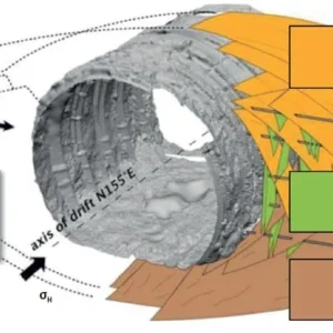
And what are the most relevant aspects of rock mechanics to design the size and geometry of a tunnel apart from Unconfined Compression Strength (UCS) and deformational properties, respectively? Well, when giving it a second and deeper thought, in-situ stresses in the rock mass have a major influence in the whole.
BIM USES AND WISHES
Focusing on specific uses concerning civil works and taking into account the maturity of modelling softwares at that early stage in preparing for project development, these uses were limited to the following:
- Definition of space requirements based on Clash Detection approach in coordination with other relevant disciplines.
- Geometry definition of the rock contour model, to estimate the need for land acquisition, to provide the needed geometrical objects to model, and to feed information to the excavation machinery at the construction stage.
- Distribution of rock support, grouting treatment, and special measures along the tunnel alignments. This information is tentative based on geological prognosis and is revised and updated depending on site observations and decisions.
- Reduction in number of drawings as much as possible, distributing them along the alignments as per the applicability of each one. All drawings were extracted from the models, except a few which were generic and project wide.
- Extraction of bills of quantities, which required postprocessing in a spreadsheet.
- Compiling and organising the geological and geotechnical information in a geometrically suitable manner.
- Input for construction machinery, moving forward to the automatisation and improving the communication between the design and the construction teams.
- Verification of the final as-excavated cross-section against the as-designed theoretical geometry by means of 3D scanned surfaces.
To comply with the bullet points listed above, the workflow indicated in Figure 6 was proposed. The project was organised in two complementary groups, avoiding duplicate information. The first group focused on non-graphical data, gathering Design Requirements and Technical Specifications. The second group focused on graphical information, involving models showing the geometrical definition and the geological conditions; this group also handled all 2D and 3D analysis models to verify the design.
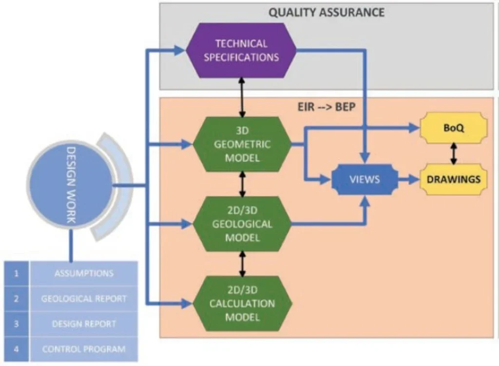
It is also relevant that every box in Figure 6 corresponds to a single file, except the Views and the Drawings, which were included in the same one. The Views are the link to the section obtained directly from the model while the drawing implies all formatting tasks, adjustments and add-ons needed to present the information as per drawing standards.
The organisation of all these files was developed in the Common Data Environment (CDE) Projectwise© from Bentley, helping to provide common guidelines, metadata, managing external references, and to track the review process.
It was also very important to define which type of information should not be included in the model. For instance, representing with detail the as-built excavation sequence or the rock support would probably lead to important deviations from the as-designed geometrical models, requiring a very time-consuming task of continuously updating the models.
‘BIMING’ TUNNELS IN HARD CRYSTALLINE
ROCK Once BIM benefits are globally accepted then comes the discussion on the degree of accuracy to which these techniques can be applied in a rock tunnel project. Is the construction process correctly represented? How many virtual objects need to be included? Could the model be misleading or misinterpreted, resulting in delays or conflicting information? These questions should be primarily considered and addressed as part of the BIM Execution Plan (BEP), adapting all the procedures to the standards and previous experiences, and considering all singularities and project specifications.
The excavation process for the Stockholm Blue Line metro extension follows the well stablished and traditional Observational Method, which implies continuous site decisions and adapting the design to the factual conditions found during tunnelling. This refers not only to the definition of the rock support and the position of the rock bolts, but also to the final heavily uneven, unpredictable in general, overbreak of the excavated rock contours as result of the blasting operations.
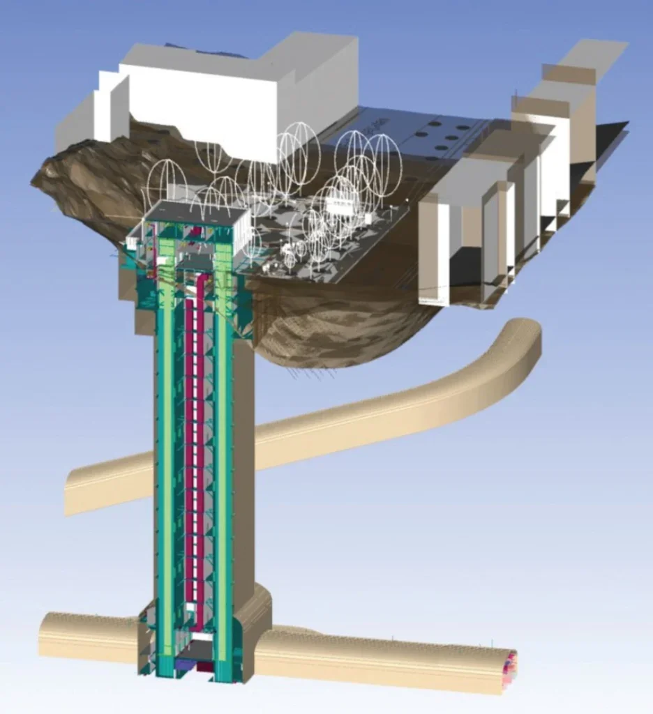
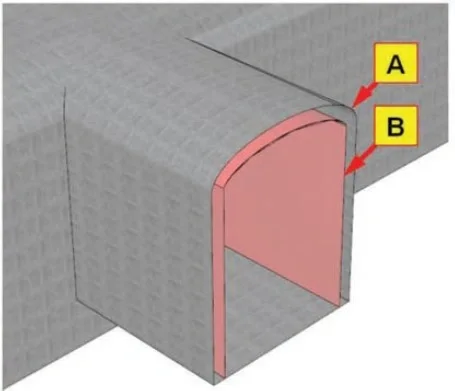
As result, in this BIM approach, it was decided that limiting details to only the LoD 200 level would be most effective, following the usual convention of lowest to highest (LoD 100 to LoD 500), as defined in the ‘BIM in Tunnelling’ recommendations by the German Tunnelling Committee (DAUB). The chosen LoD level excluded from the models the representation of specific objects of rock support, waterproof membranes and any other related element. Only the theoretical surfaces standing for the ideal rock contours plus the virtual internal space reservation were included in the models (see Figure 7).
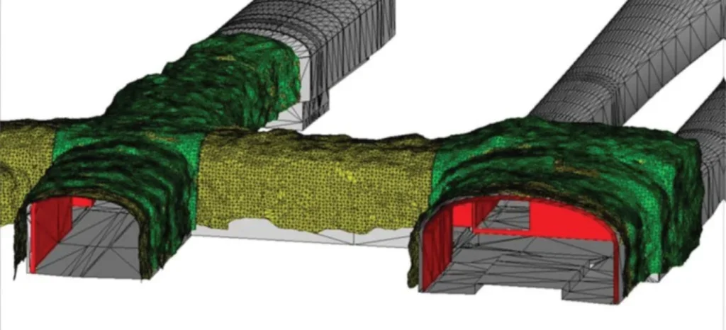
To have this concept clearly defined and communicated is vital for the rest of the disciplines, so the interfaces and connections can be designed correctly. A good example is that, on this project, the responsibility of installing all the anchors to hang the MEP trays was assigned to the civil engineering disciplines. This decision was taken to ensure that installing these steel rods would not affect the waterproofing of the system. Each of these bolts has an exact defined position and an installation tolerance. Since the as-built and theoretical profiles of the tunnel will most likely differ from each other (see Figure 8), the final position of these anchors should not be based on the theoretical rock contour model (surface A in Figure 7) without further considerations.
MODELLING GEOMETRIES
Two different types of software applications were considered to model the geometry of a tunnel at the beginning of the Stockholm Blue Line metro extension
- Based on volumes, producing Objects which are placed in the Euclidean space. By assembling and combining these objects, the model is built up.
- Topographic and alignment software, forming the tunnel by sweeping curves (typical sections) along profiles.
The models were developed using alignment software (PowerCivil© by Bentley) for the tunnels and galleries, and this was used in combination with 3D modelling at the entrances (Microstation© by Bentley).
This decision was based on the predominantly longitudinal character of the three parallel tunnels, the efficient management of the constant change of the cross sections, the simplicity of modelling multiple surfaces and volumes, and the quickness to implement geometrical modifications in both cross-sections and alignments.
On the contrary, intersections between tunnels and connecting galleries, plus generating material takeoffs, were highly time-consuming.
MODELLING GEOLOGY
In general, the geological conditions in Stockholm are straight forward in the sense that most of the existing tunnels are excavated in high-quality granitic rock mass. However, it is a challenge to accurately identify the contact between the overlying soil deposits and the bedrock, as well as to identify heavily-fractured fault zones where low cover and high pressure groundwater may exist.
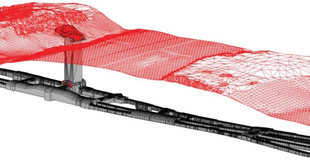
Field works, consisting mostly of recovery-core boreholes and monitored drills, were conducted to provide reliable data to model this bedrock as a surface (surface in red in Figure 10). As this rock surface establishes the limit between construction techniques, having it defined to acceptable accuracy was necessary.
Other geological features such as fault and fracture zones were decided not to be represented due to the unavoidable uncertainties in all geological models. Instead, it was decided to show the distribution of parameters relevant to tunnel execution (see Figure 10), being the main ones the classification of the cross sections depending on the span, geotechnical categorisation, use of typical and specific rock support, grouting types, and firefighting and inspection demands.
MODELLING CALCULATIONS
The ideal BIM workflow involves conducting geotechnical analyses directly on the 3D models. At the beginning of the Stockholm Blue Line metro extension project, the position with interoperability and compatibility between software applications meant that the 3D geometrical models could not be directly opened in analysis applications, and to achieve this required time-consuming pre-processing (see Figure 6). This additional effort limited the possibility of updating analysis models whenever modifications were implemented in the geometrical models.
In addition, most of the time the geometrical models included greater detail than strictly needed and became a bigger load and challenge for the calculation software. One may think that the more detail the better but, in reality, the finer the analysis mesh the longer the computing times, heavier the files and there is higher risk of getting poor results from an analysis due to local issues.
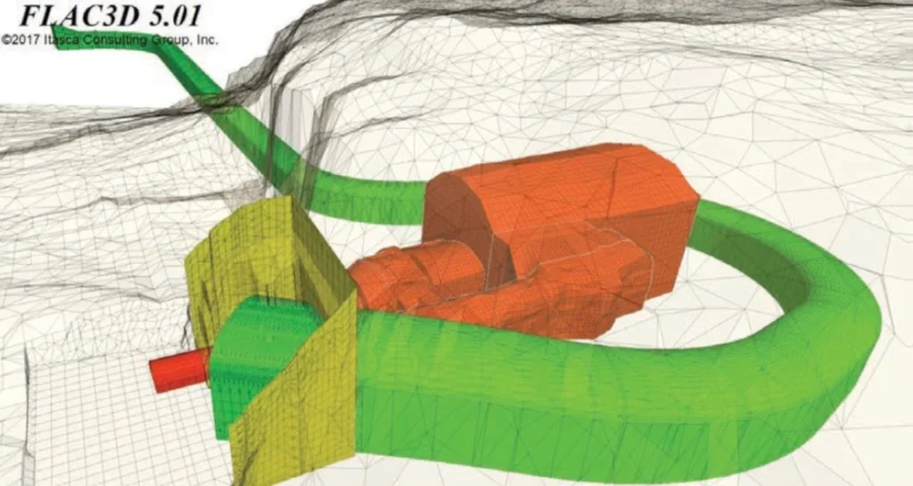
In order to address those issues, DXF format geometry files were imported in the analysis application. Then the analyst had to manually produce the calculation mesh. Most of the calculations were conducted using 2D Finite Element Numerical models, which allowed efficient updates of the analysis models, but at some locations complex 3D analyses were necessary.
AWARDS AND RECOGNITION
Typsa’s commitment in BIM methodologies is widely recognised, having been selected, alongside FUT and Sweco, as one of the three finalists at the 2016 Bentley ‘Be Inspired Awards‘ under the ‘Innovation in Rail and Transit’ category.
A couple of years later, Typsa won the ‘Infrastructure 2018 Bentley Awards’ being part of the Consortium formed by SCS (Skanska-Costain-Strabag JV) and the Design House JV (Arup-Typsa-Strabag).
The Stockholm Blue Line metro extension project has so far received an excellent sustainability rating for all its evaluated parts CEEQUAL client & outline interim award.
ACKNOWLEDGEMENT
This article wouldn’t have been possible without the support of FUT, especially from Björn Linde and Martin Hellgren. The author would like to thank our excellent Typsa technical team for its hard work, with special mention to Laura Gallego, Elena Gilarranz, Fernando Ceballos, Pablo Díaz and Mashuqur Rahman. Additionally, our gratitude to the project managers in Typsa who helped out to survive long working days: Johannes Segerpalm and Sebastián Iglesias. Teaming up with our Sweco colleagues was a very valuable experience; forever thankful to Dick Karlsson, Mats Lind and Fanny Hartvig. To finish, I would like to apologise to the many friends and colleagues involved and not involved in the Stockholm, Blue Line metro extension project who are not mentioned, the truth is that the list should be much longer.