


INTRODUCTION
The Transpennine Route Upgrade (TRU) East of Leeds (EoL) is a scheme to upgrade the railway route between York and Leeds, with Project E1 going from York to Church Fenton. This scheme includes electrification, line-speed and capacity increases along with the associated works to enable them. Project E1 has reviewed 53 structures along the section route.
TRU EoL is being delivered by the TRU East Alliance, formed of Network Rail (as both Client Organisation and participant), J Murphy and Sons, Siemens, Systra, and Volker Rail. Active Tunnelling were appointed as sub-contractors to J Murphy and Sons. They provided specialist Early Contractor Involvement (ECI) and were also appointed for construction of the works following a competitive tender of the Approved for Construction Design. Aecom provided Environmental support to Network Rail in respect to flood modelling and obtaining consents for the works.
Part of the works within Project E1 required the replacement of an existing flood balancing culvert to provide a structure suitable for the increased frequency of rail traffic – whilst maintaining the transfer of flood waters across the railway embankment within a Flood Zone. The local area provides flood water storage for the River Wharfe.
The existing culvert – NOC/23, and comprising 119-year old brick twin arches – showed signs of settlement since 1947 due to subsidence from local ground conditions. The local ground is mostly peat and has an underlying dissolution feature. The structure is undergoing regular remote monitoring due to its condition but has required replacement as part of the project’s need to increase the frequency of railway traffic.
With the proposed works located in a flood zone, consents approval was sought from the Environment Agency for both the temporary compounds and the permanent works. The consenting process began in 2020 for the works, located 16.2km south of York. The flood zone made the proposed works challenging due to unforeseen weather conditions and potential rising groundwater levels.
The replacement culverts would be circular pipes and jacked into position. Thrust and reception pits would be completed on opposite sides of the embankment, ahead of the pipe installations. This order of works was crucial to balance the movement of water and allow the permanent works to be undertaken.
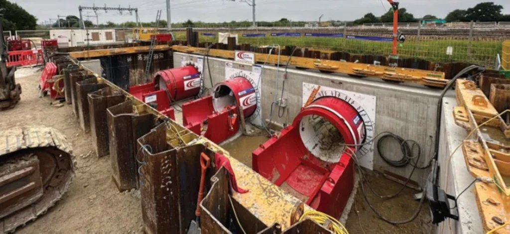
Three small diameter tunnel boring machines (TBMs) would work simultaneously side by side, jacking the pipes beneath the four-track railway.
The works at the embankment were undertaken in August 2023 for optimum weather conditions due to the site being located within the flood plain. They were completed in 54 hours during which the three pipes were safely installed below sequential line closures, with two lines open for a total of 45 hours to allow the railway to remain open to trains to achieve minimal disruption to services.
The tunnel installation was successfully completed on time throughout without overrun disruption to operational traffic and there were no accidents or incidents. This paper covers the design and installation works associated with these structures, with a particular emphasis of the permanent works designer’s remit.
EXISTING STRUCTURAL ARRANGEMENT
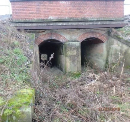
The twin-arch flood relief culvert, NOC/23, was built in 1840 to carry the Leeds rail lines, and then it was reconstructed in 1903 to accommodate the Normanton Lines. The superstructure comprises a pair of brick arches and the substructure has concrete wingwalls and foundations. The structure is owned and maintained by Network Rail and was subject to regular additional monitoring, being undertaken due to significant settlement of the Up Normanton end of the structure. Subsidence had been taking place under the Up and Down Normanton lines since 1940 and this has resulted in increased ballast depths. The headwall on the Normanton side was extended to allow placement of ballast to maintain track geometry.
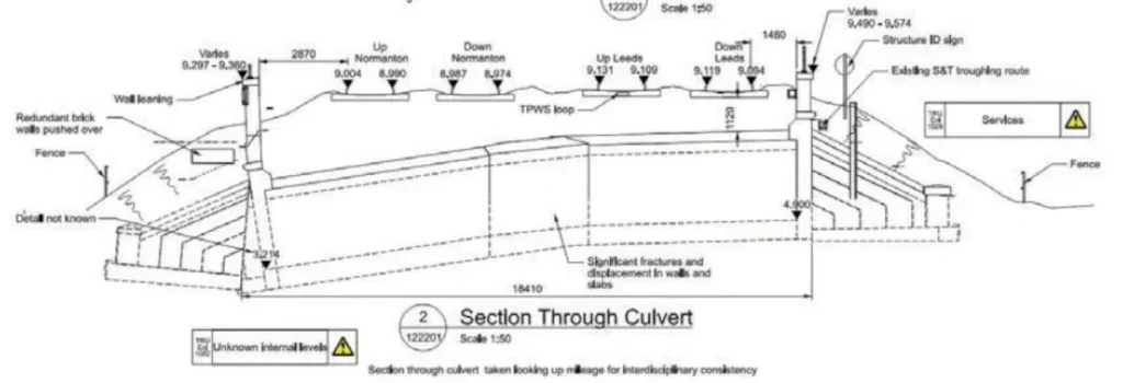
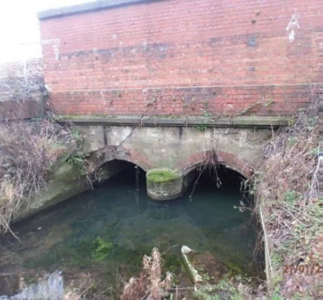
Between the Leeds and Normanton lines there is a significant fracture and displacement within the walls/ slab (Figure 3). The invert of the culvert on the Up Normanton outlet is 3.215m AOD and on the Down Leeds inlet it is 4.9m AOD; a level difference of almost 1.7m as a result of significant differential settlement along the structure. The Normanton side is constantly under standing water.
EXISTING GROUND CONDITIONS
The top of the railway embankment is made up of track bed (ballast, ash and sand) supported by nonengineered fill that was claimed from the local area during construction. The embankment itself consists of a mixture of coarse and fine deposits.
The embankment was originally constructed to carry two tracks (Leeds lines) and then extended to carry the Normanton lines. This extension appears heterogenous in construction and material and a potential pathway exists between the formation of the embankment materials. Ground investigation (GI) at the embankment was a combination of intrusive and geophysical methods. The GI confirmed the presence of a high plasticity, exceptionally low strength clay with a high organic content (indicating peats). This soil type is highly compressible and therefore is susceptible to settlement.
An additional issue within the ground is further settlement occurring due to dissolution features caused by groundwater moving through the bedrock. This will be an ongoing future issue in the area and future settlement cannot be accurately predicted. This uncertainty combined with the underlying peat means that any structures built at the same location will undergo unpredictable settlement.
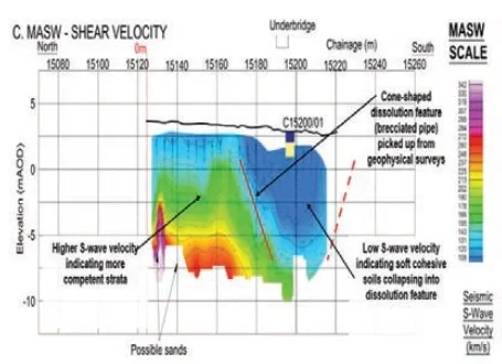
Seismic geophysical surveys captured the depth and extent of the peat and soft clay. Shear waves (S-waves) from the survey demonstrated the presence of a buried sinkhole feature, whereby dissolution within the bedrock resulted in the soils above (alluvium and peats) having collapsed into the location (Figure 6). This feature is likely to be causing the structure and embankment to displace vertically.
The dark blue colouration in Figure 6 shows a distinct area of slow S-wave velocities in a cone shape, indicating the buried sinkhole feature. In Figure 7, more competent strata can be seen for the higher S-wave velocities, shown in the lime green band, indicating a deep feature of compressible soils at the location of the existing structure.
As a result of the poor ground conditions, the new structure was moved 60m north to where more favourable ground conditions were identified by ground investigation.
PROPOSED STRUCTURAL ARRANGEMENT
The new culvert structures comprise three 1.8m-diameter concrete pipes, 18.4m long, located to the north of the existing culvert. Their total cross sectional area matches that of the existing brick culvert, as required from the flood modelling undertaken by Aecom., which means future flood events will remain closely related to past events, including facilitating flood balancing either side of the railway embankment. Spacing between the pipes was set out to prevent overlapping settlement/heave during installation. This assessment was undertaken by Active Tunnelling in the early contractor involvement phase.
The TBMs began in the thrust pit located on the East side of the railway embankment and were received in the reception pit opposite. The placement of the pits was aligned with available possessions, with the Normanton (east) being tunnelled under initially to coincide with the first part of the possession plan.
Successful integration and collaboration was required in the initial stages of detailed design to enable seamless construction of all elements.
CONCRETE TRENCHES
The existing structure is a low point in the area with an invert of 4.9m AOD. As the flood waters can flow both ways, the invert level had to be maintained for the new pipe culverts and troughs. Where minimal retention was required, ditches were used to continue the flow of water.
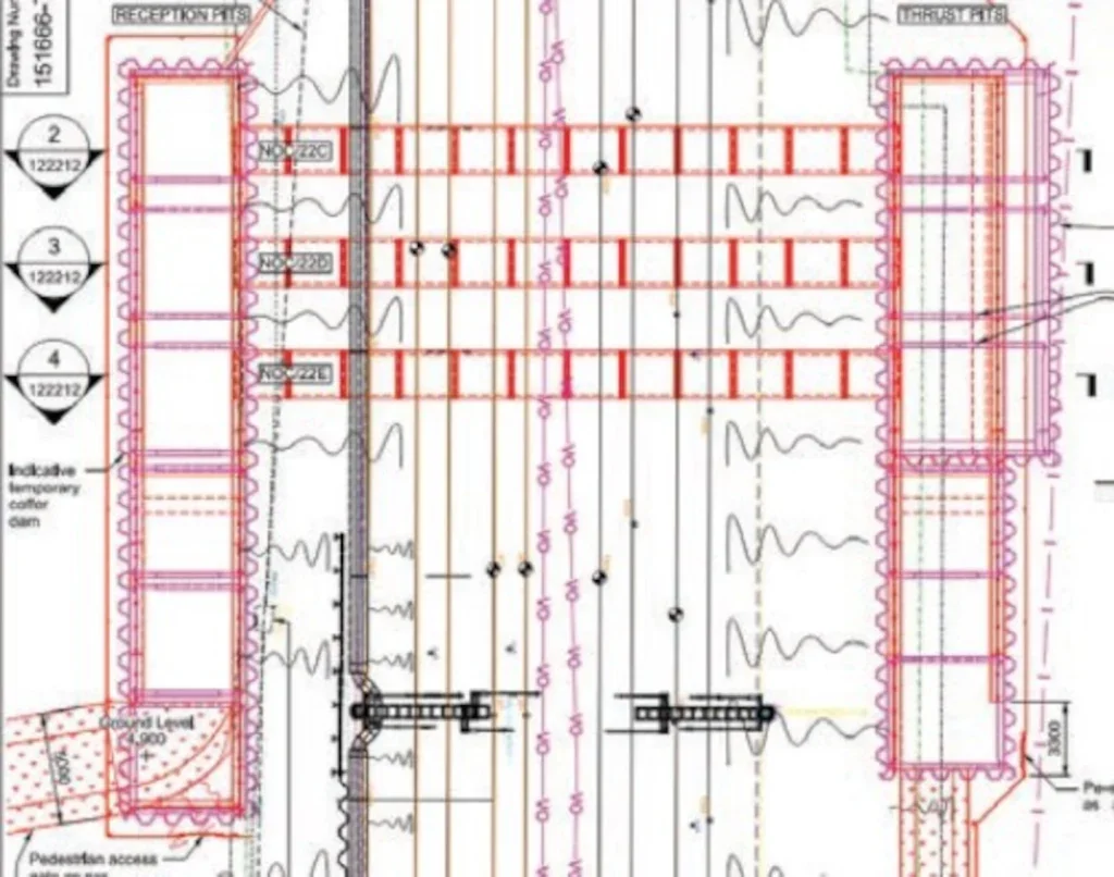
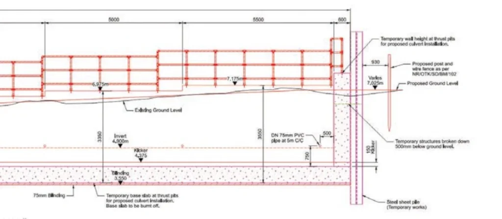
Figure 8 shows the proposed works. The colour scheme comprises: black as the existing structures; red is the new permanent structure; and magenta is temporary works.
FLOOD MODELLING
As the structure is within a flood zone, a consent application was required to infill the existing brick culvert structure and construct its replacement. The Environment Agency requested three culverts and also a full scheme flood modelling, including changes to three nearby culverts within the River Wharfe Floodplain. The model reviewed land measuring 275km2 in order to understand how the area will be affected more widely. Flood depths of up to 2.5m have been recorded outside of the River Wharfe.
Aecom undertook the flood modelling exercise to support the consent application. The direction from the Environment Agency was to retain the current situation of flood management in the area as closely as possible. This led to several requirements for the detailed design, including confirmation of the cross-sectional area required for the culverts and the materials of the trenches.
Sensitivity analysis during the flood modelling concluded that there would be no increase to flood risks at any vulnerable receptors.
Weekly meetings took place between the detailed designer and flood modelling/consents team to confirm that any design changes would not affect the modelling/ consenting process. The timescales for the Environment Agency reviewing the flood modelling and consent were such that a number of design choices had to be set in the detailed design ahead of the finalisation of the detailed design.
REINFORCEMENT AND TEMPORARY WORKS
The reinforcement design between temporary works and permanent works had to be carefully planned to allow seamless integration during construction. Various techniques were used and one of the most critical was splitting the reinforcement into stage 1 and stage 2. The first stage was everything required for the jacking and thrust pit works ahead of the pipejacking. The second stage included the final structure once the sheet piles were extracted. The splitting of this design into two stages allowed for procurement of relevant materials to allow for the construction of the culverts as well as fully integrating the pipejacking stage into the permanent works.
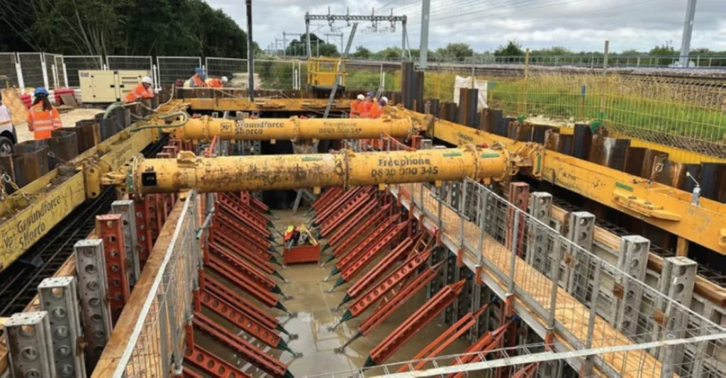
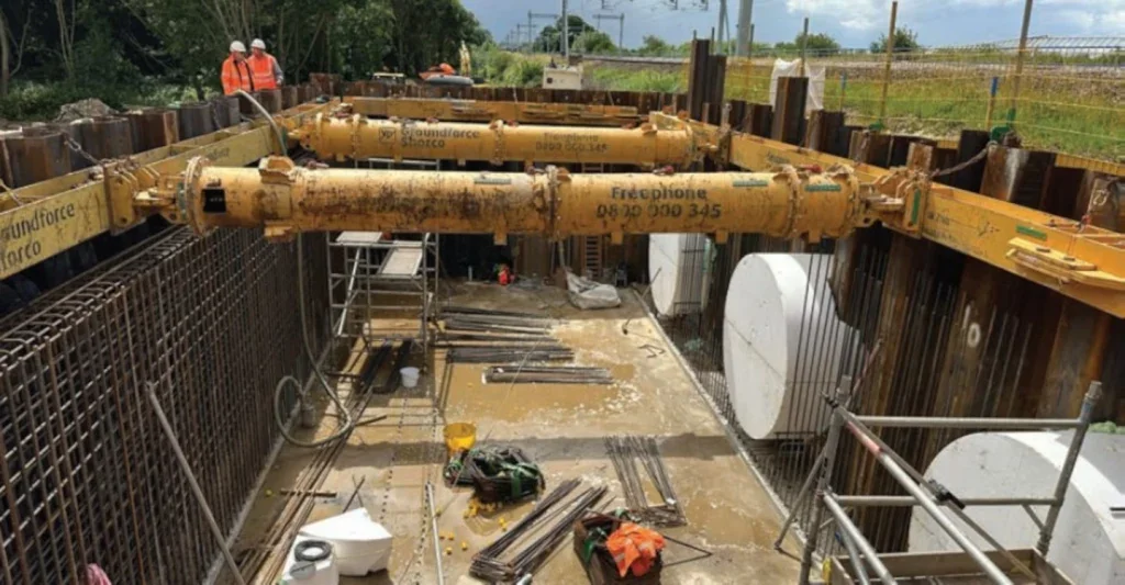
To provide a clear working area, reinforcement couplers and stop ends were used to connect the Stage 1 and Stage 2 reinforcement. This prevented reinforcement laps from being exposed during the jacking works. Figure 9 and Figure 10 show the temporary works required during the construction of the thrust pit. Props were installed between the temporary sheet piles whilst the concrete walls and base slab were cast. The propping system was later removed to allow the installation of the small diameter TBMs.
A clash was identified between the vertical B20 L bars in the slabs and wall interface and the propping system during a construction review meeting. To prevent delays to the pour of the slab, an appropriate lap length calculation was undertaken that allowed the existing bars to be cut around the props and additional straight bars provided to lap onto once the propping frame was removed. This is an example of the effective collaboration between all parties to resolve challenges encountered during the works. During a site visit to view construction progress, a steel fixer provided constructive feedback with regards to detailing radial bars around the pipe openings. The insight into challenges of working with long sections of radial bars as opposed to overlapping straight bars will contribute to solidifying the relationship between designers and contractors.
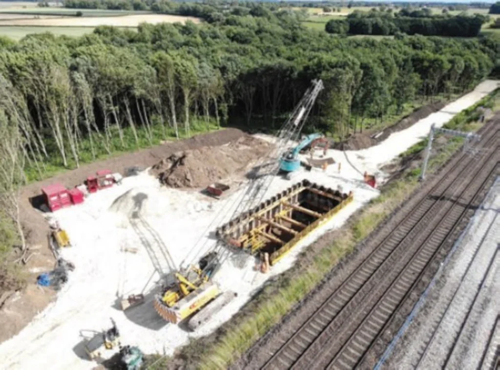
Figure 12 shows the reinforcement and temporary works for the back wall of the thrust pit. This reinforcement was checked against the jacking loads provided by Active Tunnelling. The jacking loads from the TBMs resulted in a hogging moment generated within the base slab of the pit. Larger reinforcement bars in the top face of the slab (B20’s) were installed to resist this moment. Similarly for the back wall of the thrust pit B20’s were used in the front face. The reinforcement was a demonstration of integration between temporary works and permanent works.
A shear key was introduced into the temporary design by Active tunnelling to increase the passive resistance from the soil during jacking operations. The shear key was connected to the base slab with reinforcement designed by the temporary works designer but also transferred loads into the permanent slab beyond the shear key. Figure 11 below shows the different interfaces between permanent and temporary works. The temporary sheet piles shown in magenta formed the cofferdams which were used to assist with groundwater. The piles minimised working time required with machines at the site adjacent to the railway line. A temporary base slab was also constructed which would eventually be burnt off.
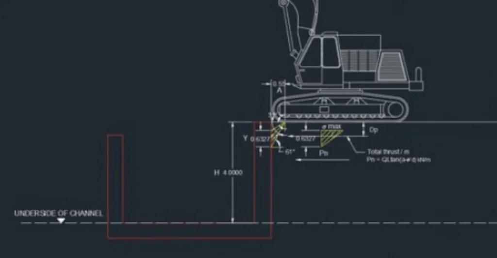
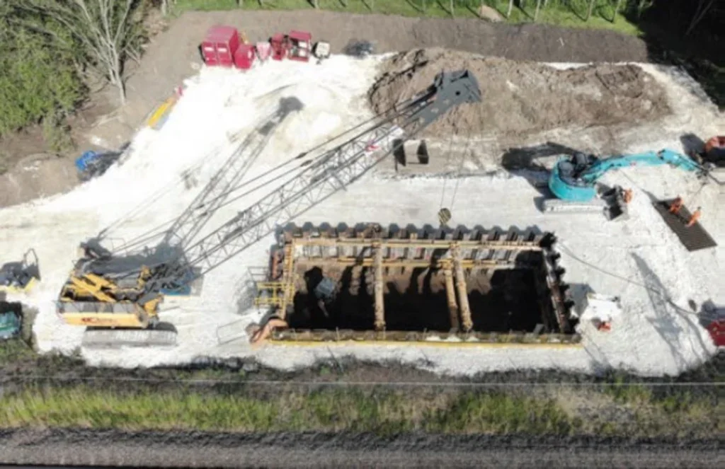
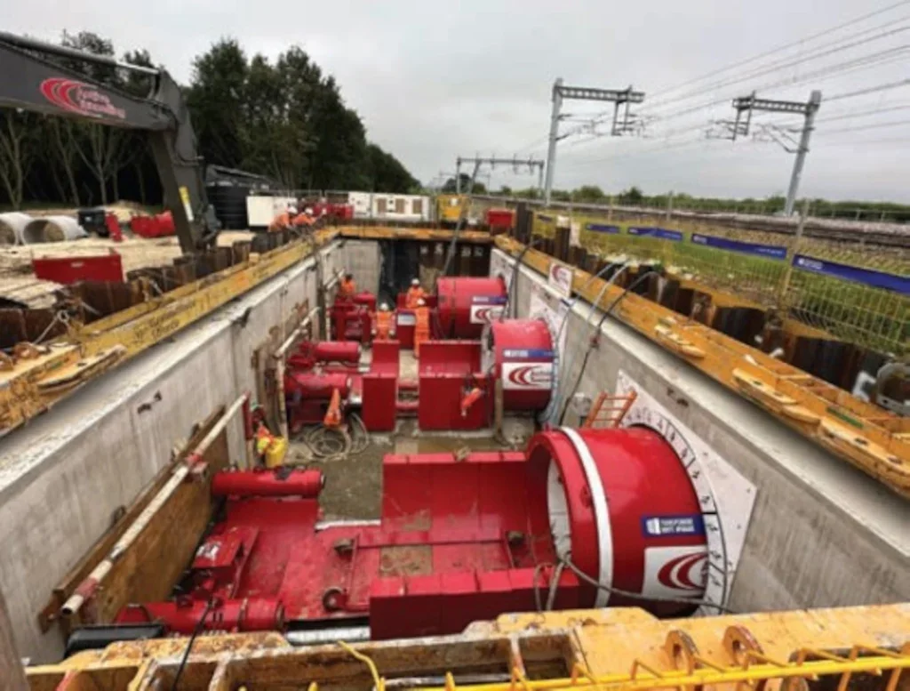
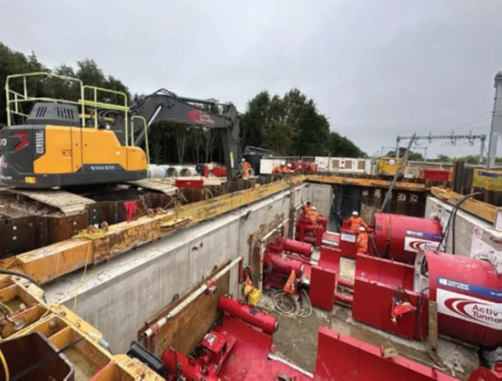
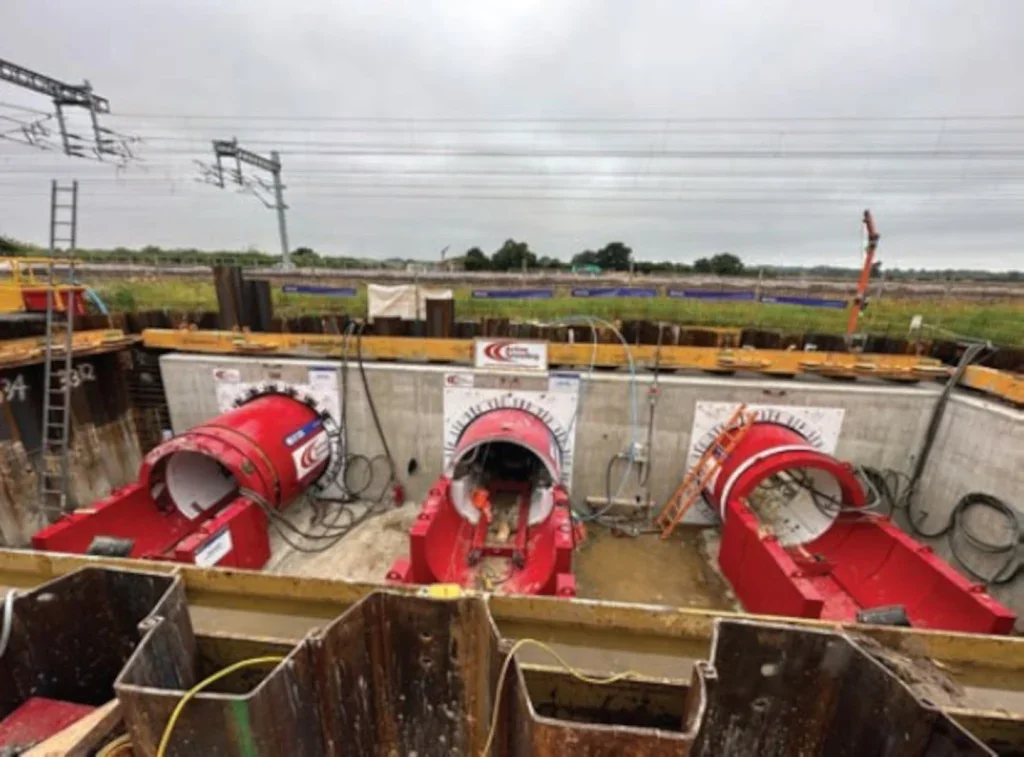
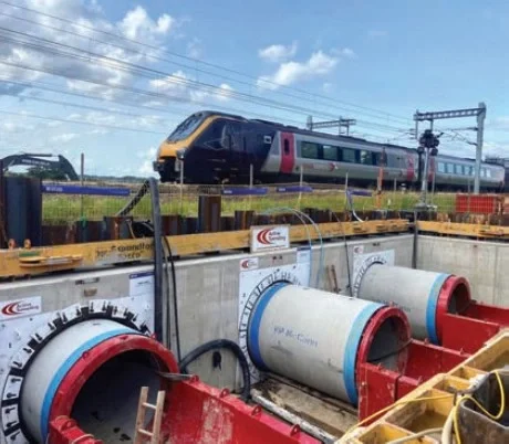
Figure 13 shows the three TBMs installed within the thrust pit. These machines embedded themselves into the embankment, outside of the track support zone in readiness for the possession being granted. Figure 14 shows the jacking plates required on the back wall to spread the load from the machines. The jacking loads were checked against the permanent design in the form of both hand calculations and analysis software. Figure 15 shows a view from the thrust pit looking towards the reception pit on the other side of the railway. The sheet piles adjacent the railway embankment will remain in place with the other sections being withdrawn once the concrete sections reach the specified design strength.
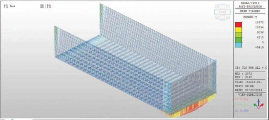
Figure 16 shows the 50 tonne crane and two 42 tonne excavators adjacent to the thrust pit. These machines were key to the successful construction of both pits, which ensured the construction works during the possession were achievable in confined working environments. To construct the pits and the compound, a temporary purchase of land was required. A large number of trees were removed to facilitate the construction of the compounds. To meet Network Rail’s net biodiversity increase objectives, all the trees will be replanted and including an additional 10%.
As part of the compound construction, track matting was used to allow for vehicular access. This option negated the need for 3000 tonnes of imported stone. Additionally hybrid plant, solar panel site cabins and tower lights were used.
CRANE AND EXCAVATOR TEMPORARY WORKS CHECK
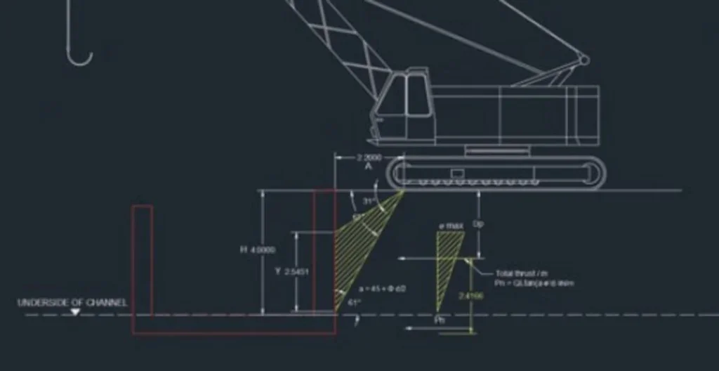
Close collaboration was required between Systra (Principal Designer) and Active Tunnelling (Subcontractor to Principal Contractor) to achieve the construction works. One of the checks completed was to consider the effects of a 42 tonne excavator and a 50 tonne crane in close proximity to the pits. The crane was required to lower the tunnel boring machines into place. The excavator was required for withdrawal of the temporary sheet piles as well as other duties. Refer to Figures 17-19 for load diagrams and analysis results.
The crane and excavator specifications were provided by the Principal Contractor (J Murphy and Sons). The machines respective weights were converted to calculate lateral and vertical dispersion of finite line loads for calculating horizontal surcharge pressures. Loads were checked using finite element (FE) analysis software, MIDAS. The calculations determined that the loads generated from the self-weight of the machines were less than the maximum bending capacity and shear force capacity of the walls/base slab. A minimum offset from the centreline of the machines’ first axle to the pit was provided to the Contractor as a safe working limit.
INFILL OF EXISTING STRUCTURE
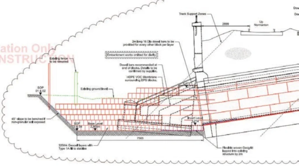
Figure 20 shows the proposed infilling of the existing structure. These works would remove the future maintenance liability of the structure.
Foam concrete was initially proposed to undertake the infill of the structure in line with standard Network Rail details. Foamed concrete is a lightweight fill suitable for infilling stable structures as a void filler but has a compressive strength that lowers as it gets lighter. With settlement likely to be ongoing, a material was required that would aid both the long term stability and structural integrity of the existing culvert. Through design development it was identified that expandable polystyrene (EPS) blocks contained within a high performance hydrocarbon and chemical resistant liner was the best option. This provides a material with a high compressible strength and low density to reduce long term settlements from the infill material. A combination of dowel bars and flexible woven geogrids allow the infill blocks and the embankment to work together globally.
CONCLUSION
This paper demonstrates that it is possible to install three culverts using tunnel boring machines, under an operational railway, during a 54 hour possession. A total of 615 tonnes of earth was removed during the possession. This was achieved by integrating temporary works and permanent works designs. Weekly meetings with key stakeholders and the construction team allowed me as the designer to understand key risks and construction best practice. Weekly discussions with the geotechnical team also played a huge role in the successful construction and delivery of the scheme. Extensive physical and non-physical ground investigation, discussions with the tunnelling contractor and operating as an Alliance made this scheme possible. Whilst three culverts have been sequentially installed adjacent to each other, we believe this is the first time that three culverts have been jacked simultaneously.


