


INTRODUCTION
Maintaining water infrastructure is analogous to painting the Forth Rail Bridge. The moment you think you’ve finished, you have to start again. The reality is that much of the UK’s water infrastructure is quite old; is trying to cope with a population far beyond that it was originally designed for; and, is under assault from both the natural and built environment. And that’s before we start to deal with the wee beasties that have decided there’s nowhere better to live.
Broadly speaking, when considering the maintenance and rehabilitation of sewers and water tunnels the issues fall into two categories: first, there are matters relating to the condition of the fabric of the asset; and second, there is the question of whether obstructions are compromising how efficiently the asset is performing.
In this article, we will illustrate the different challenges we face across the UK undertaking maintenance, refurbishment and upgrade programmes to keep sewers and water tunnels flowing freely.
WHAT CAUSES DETERIORATION IN THE FABRIC OR THE PERFORMANCE OF SEWERS AND WATER TUNNELS?
Sewers rarely deal with only sewage. Across the country, everyday activities – washing dishes or clothes, bleaching toilets – add a potent cocktail of chemicals to the already generous quantities of waste and effluent to create two principal issues.
First, hydrogen sulphide gas mixes with the water and creates sulfuric acid. In slow flows, the acid is able to lay on the structure and accelerate the deterioration of the concrete fabric and steel reinforcement causing leaks and failures.
Second, fats are poured down sinks during cooking and washing up. These fats solidify into particles as they cool and the particles collect together. Over time, they gather together in such great numbers that the sewer flows are slowed allowing even more to gather until the sewer is blocked.
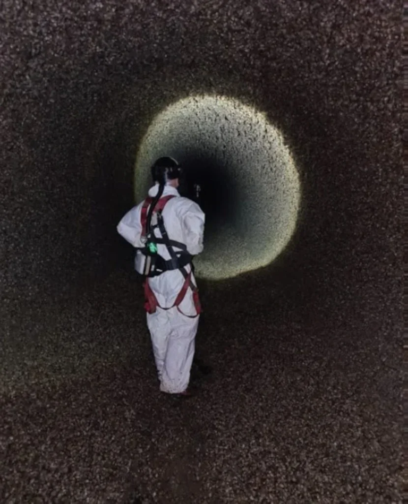
For raw water tunnels, it is a different story. Here the threat is not from fats but from silts. The silt is natural and comes from our rivers, suspended in the water naturally. When abstracted, most of the silt is allowed to settle out of the water in reservoirs but some will always manage to find its way into the tunnels. Unfortunately, alongside the penalty to water tunnels’ hydraulic performance, the silts bring with them another problem – invasive mussels.
The most widespread culprit, the Zebra Mussel, finds water tunnels the perfect habitat in which to live. They attach themselves to tunnel walls, often in such dense concentrations that they begin to act as a barrier to the flow of silt – which instead gets trapped around them. With more silt comes more mussels, and with more mussels there is more silt – creating a true vicious circle, at least from the point of view of the efficiency of the tunnels (the mussels may not agree).
It is worth bearing in mind that these tunnels are often running at great depth and at high pressure (the same as at the reservoir head) so the mussels and silt, like plaque in arteries reduce the efficiency of the system and encourages water to escape.
HOW IS THE DETERIORATION ASSESSED AND PLANS FOR ACTION DEVELOPED?
Corrosion in large diameter cast iron water mains is difficult to detect but can lead to major bursts. A thorough inspection of an asset will typically require its isolation. Considerable work is currently being done to explore new technologies that will allow investigation of conditions “’n-pipe’ without any risk or supply interruption to customers.
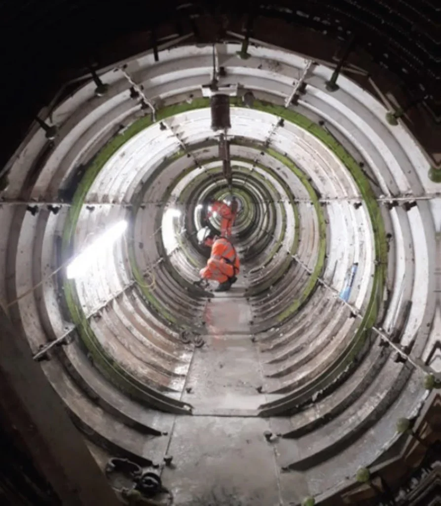
Under the Reservoirs Act 1975, all raw water tunnels over a certain size and flow need to be inspected for structural stability at regular intervals.
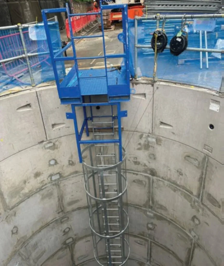
To make this possible, the tunnels need to be removed from service, isolated, drained and then cleaned of all debris to expose the internal linings of the tunnel for inspection. This is always the largest and most high risk part of the work.
Once cleaned and, depending on the requirements of the inspection, the team will use a combination of survey methods including:
- Visual inspection;
- Tap survey;
- Line and level surveys;
- Laser scan 3D surveys;
- ROV surveys; and,
- Internal GPR surveys.
At this stage, the reservoir engineer will produce a report which will evaluate the risk to the network presented by the condition of the asset and make recommendations on necessary works.
MEETING THE CHALLENGES
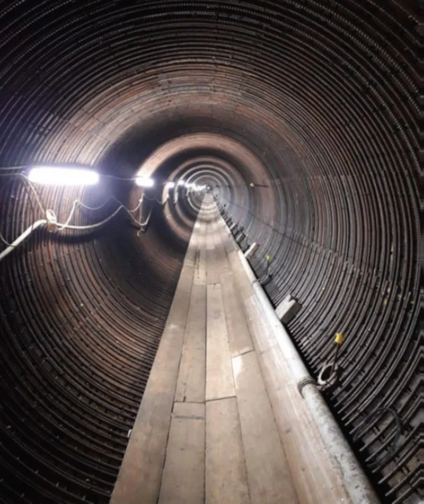
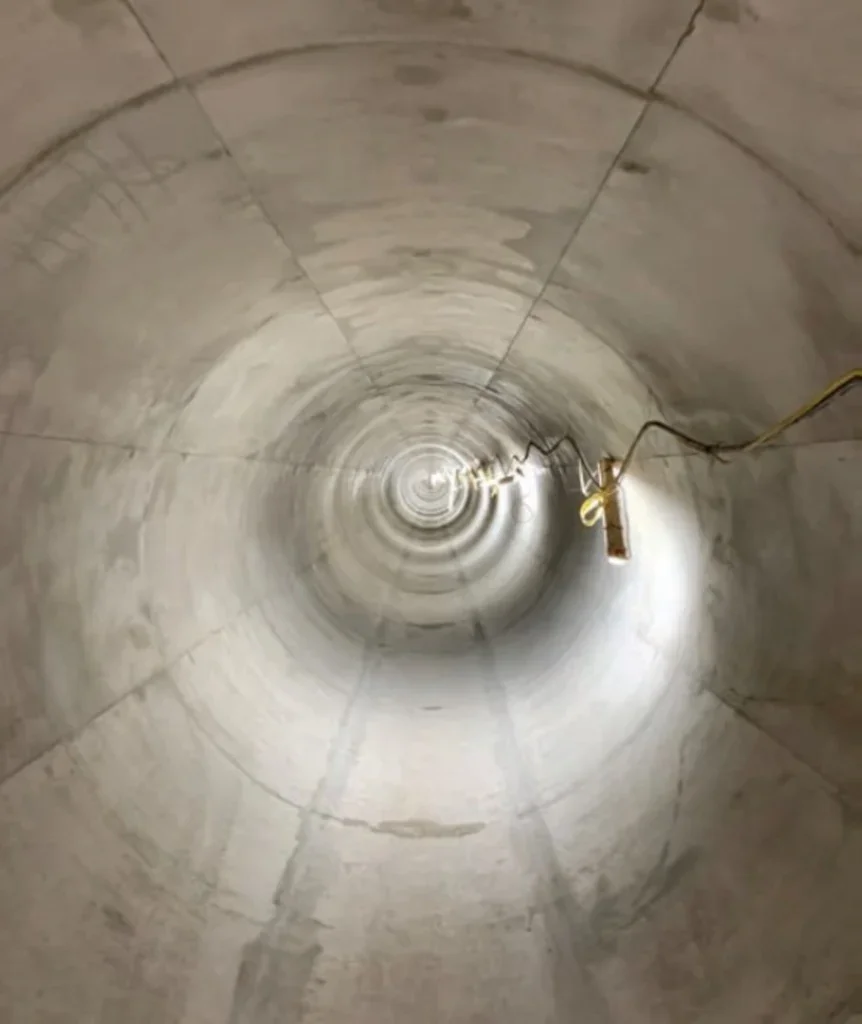
Barhale has recently been appointed to a package of schemes under Thames Water’s Raw Water Tunnel Inspection & Refurbishment Programme, which provide a good example of the sort of remediation and maintenance work necessary to keep the water flowing.
Under this contract, we are inspecting 35km of raw water tunnels across West and North London. We are removing debris, silt and invasive species.
Zebra Mussels have formed substantial concentrations across the network and it is anticipated that, in the most affected tunnels, as much as 140m3 of mussels will be removed.
Once cleared, the tunnels will be inspected and any structural repairs will then be carried out.
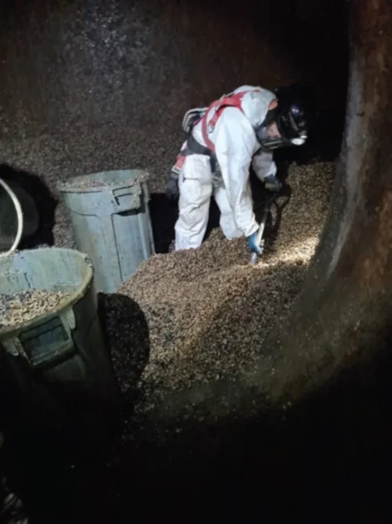
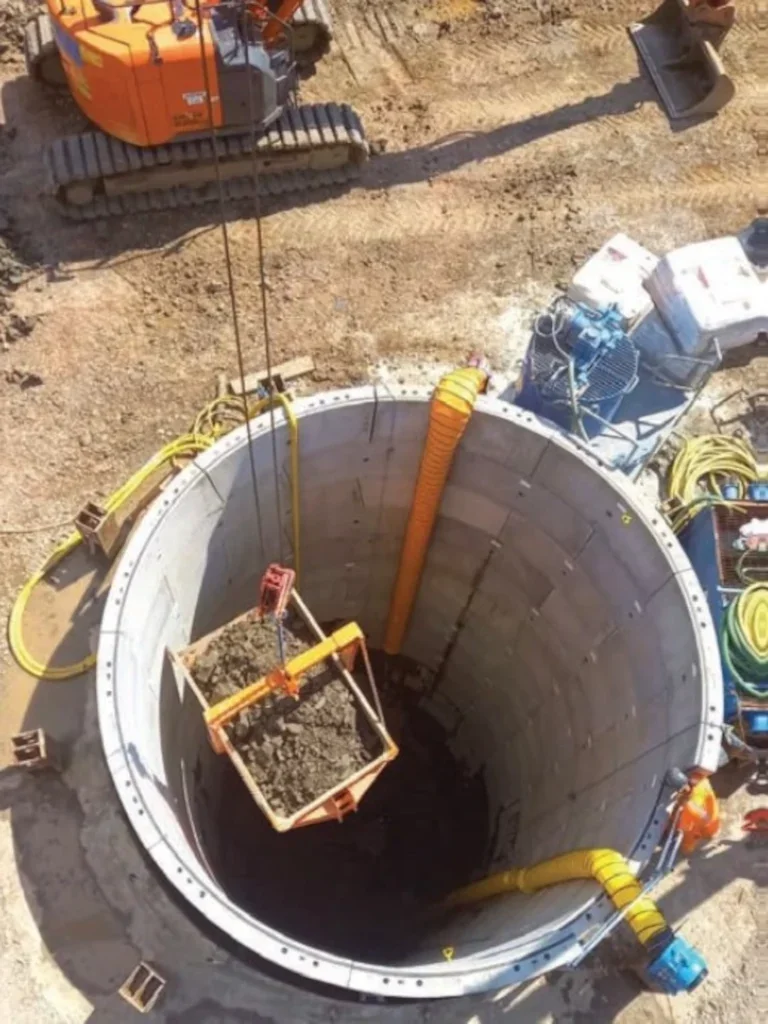
Although several methods are used for removing the silts and mussels, Barhale’s preferred method is by high suction vacuum.
As the waste is essentially a saturated particulate, when moved it easily turns into an unmanageable slurry. By using high suction vacuum, the waste is removed and contained in pipework, until it reaches the surface, and deposited directly into a storage tank. When filled, it is discharged directly to a waste tanker through pipework.
This method means that the waste is fully contained from the extraction point right through to the final discharge location and so eliminates the risk of cross contamination or pollution of the local areas.
In longer tunnels, where suction is not possible (because of velocity loss through the length of the suction pipework), the suction pipework is ‘broken back’ to a distance where the suction velocity is still good. In this instance, waste is transported manually (for example by scrapers, barrows or trollies – although efforts are always made to mechanise the operation) from the location of the engineering teams back to the head of the suction pipes.
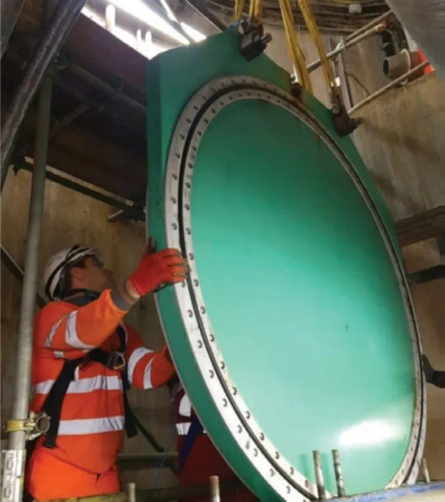
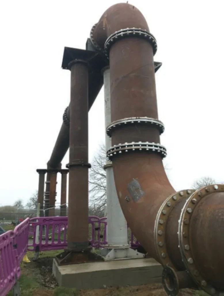
Mussels were also a minor problem in the outlet tunnel at the QEII Reservoir in South West London, where we were called in to carry out an £11m tunnel relining contract to strengthen the aging 1.06km-long inlet and 0.9km-long outlet tunnels to prevent leakage and to reinforce the integrity of the reservoir.
The inlet and outlet tunnels run under the embankments of three critical reservoirs, busy roads and property so the integrity of these tunnels is of the highest importance to Thames Water.
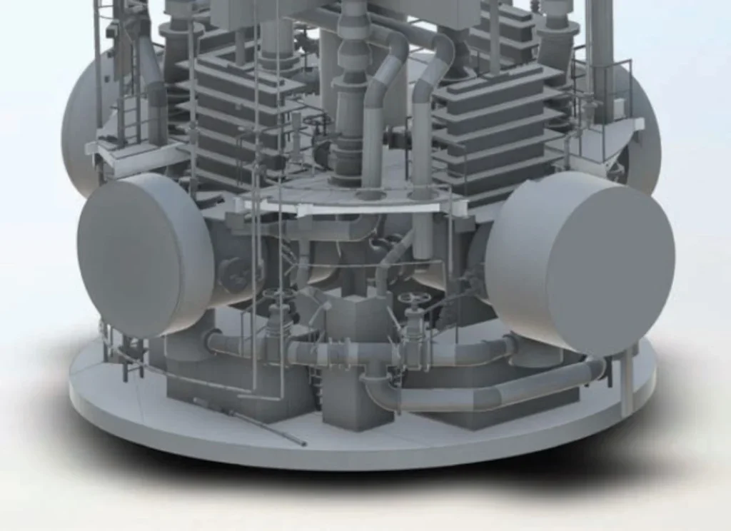
Submersible ROV CCTV and Lidar surveys were used to survey 72” internal pipework at the base of the reservoir that formed part of the outlet system. These digital surveys helped Thames Water to understand the hydraulic modelling of the reservoir pipework.
Temporary shafts had to be constructed over the existing tunnels for access. By creating 3D CAD models the temporary works team was able to break down the phases of work and specific requirements, helping to deliver a more efficient and safe solution. The models also provided visualisation of the works for the operations team and allowed a simpler interface between the temporary and permanent works to be designed such as the support required for breaking into the two tunnels.
To protect our workforce relining the tunnels, we worked collaboratively with Thames Water to complete and implement a robust and thorough isolation procedure. This included making sure that every valve and outfall into the tunnels was double isolated – with primary and secondary physical and electronic isolations.
The molluscs and debris were cleared before both of the tunnels were relined with poured concrete, with steel fixing done ahead of the concrete work. Shutters were installed insitu by the team, with concrete poured and cast in place.
Operational challenges are not confined to the condition of tunnels and their residents. Sometimes internal valves can form an obstacle in the tunnel. Gate valves are not so much of an issue as, when open, they leave nothing within the tunnel bore. Butterfly valves on the other hand, cannot be passed safely without having a specific Safe System of Work (SSOW) to do so. While this situation is made slightly easier by the fact that most of the butterfly valves on the network have access hatches into the tunnel on either side of them to allow the workforce entry, these are often at great depth and difficult to reach.
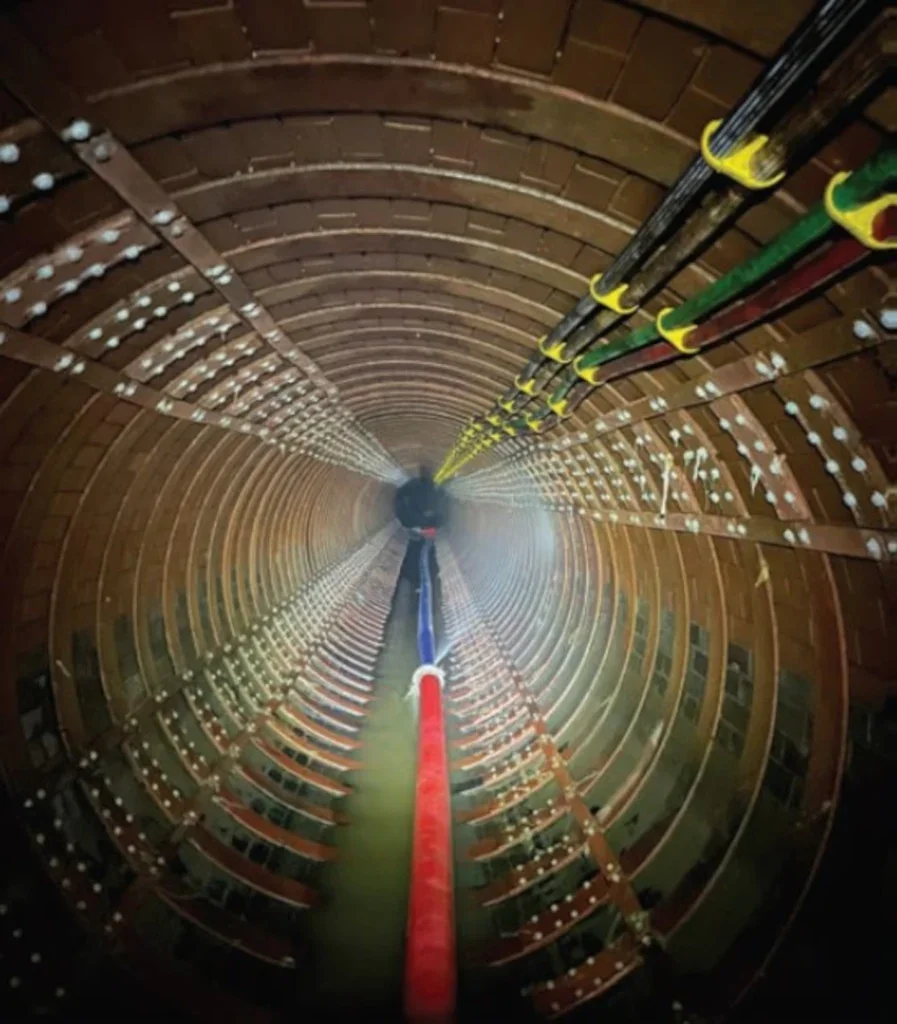
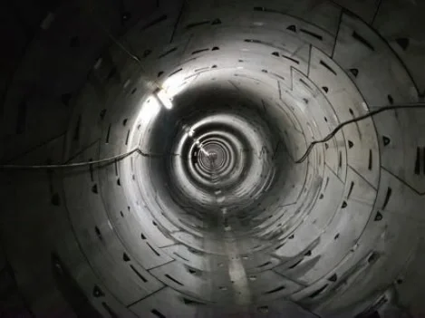
Perhaps the biggest and most important of our maintenance challenges relates to the Thames Water Ring Main, the 80km-long tunnel running beneath London and supplying approximately one-sixth of the capital’s daily water requirements.
The Ring Main’s critical role in London’s water supply means that nowhere is the need for careful outage management better illustrated and we work closely with Thames Water to ensure that we maximise the opportunity each time a section of the tunnel is isolated and drained.
Maintenance work here relates to both the tunnels and the 21 shafts that drop down onto the ring main, the deepest of which is more than 65m.
The Ring Main has a capacity of 405 million litres of water – the equivalent of a large reservoir – and it is important for both distribution and storage. Outage management is critical and we collaborate closely with Thames Water to optimise resource deployment while sections of the Ring Main system are isolated and drained to allow work to be carried out.
The collaborative approach has yielded some impressive results. The works between Surbiton and Merton presented a very difficult outage of the Ring Main, initially earmarked for six weeks. Through collaboration with Thames Water, the team worked to an accelerated 24/7 programme, which reduced the programme to just 10 days. This enabled the client to restore the section to service and to meet the surge in customer demand for water during a key Bank Holiday weekend.
For the first time, double sections of the Ring Main are being isolated simultaneously. In 2021, the Barrow Hill – Park Lane/Park Lane – Battersea sections were carried out as a single outage, delivering significant efficiencies. Two outages originally programmed for 10 weeks were compressed to one, delivered in eight weeks – including two weeks of significant tunnel repairs not originally programmed. This delivered a performance efficiency saving of 33% and a carbon saving of approximately 11%.
We have recently been working to replace more than 270,00 White Caps, the push-fit caps covering the lifting eye sockets on each tunnel plate with new, screw-fit types as part of the ongoing maintenance programme.
To improve future management of the Ring Main, Barhale has embarked on a project to capture the entirety of the asset in a digital map. In terms of scale, this will be one of the largest digital tunnel mapping exercises ever undertaken. Among other factors, it will lower health and safety risks by reducing the need to negotiate the very long underground transits and confined space working. It will allow:
- Remote management, allocation of tasks, supervision, and review of work giving a real-time progress status snapshot;
- The replacement of paper-based safety and quality records;
- Digital inventory of assets and parts, simplifying future maintenance;
- Assets and equipment can be procured without multiple inspections; and,
- Reduced intervention and reduced carbon footprint.
- As previously noted, hydrogen sulphide (H2S) is a major cause of problems for the UK’s sewer network. At our project at Potters Way, working as part of Anglian Water’s @one Alliance, significant corrosion of the original concrete pipes had been caused by H2S released from the sewage flows.
Investigations revealed that 430m of concrete pipe and 85m of GRP pipe needed to be renewed. We were able to come up with a solution that allowed the pipe to be refurbished without having to excavate and replace the entire pipeline.
Traditional diversion and replacement would have had a major impact given the site was alongside a busy road and within an environmentally sensitive area. By using Cured-in-Place Pipe (CIPP) relining and working within live flows, we were able to reduce project costs and the level of disruption to residents and road users.
It is anticipated that the works carried out will prolong the life of the sewer for at least another 50 years.
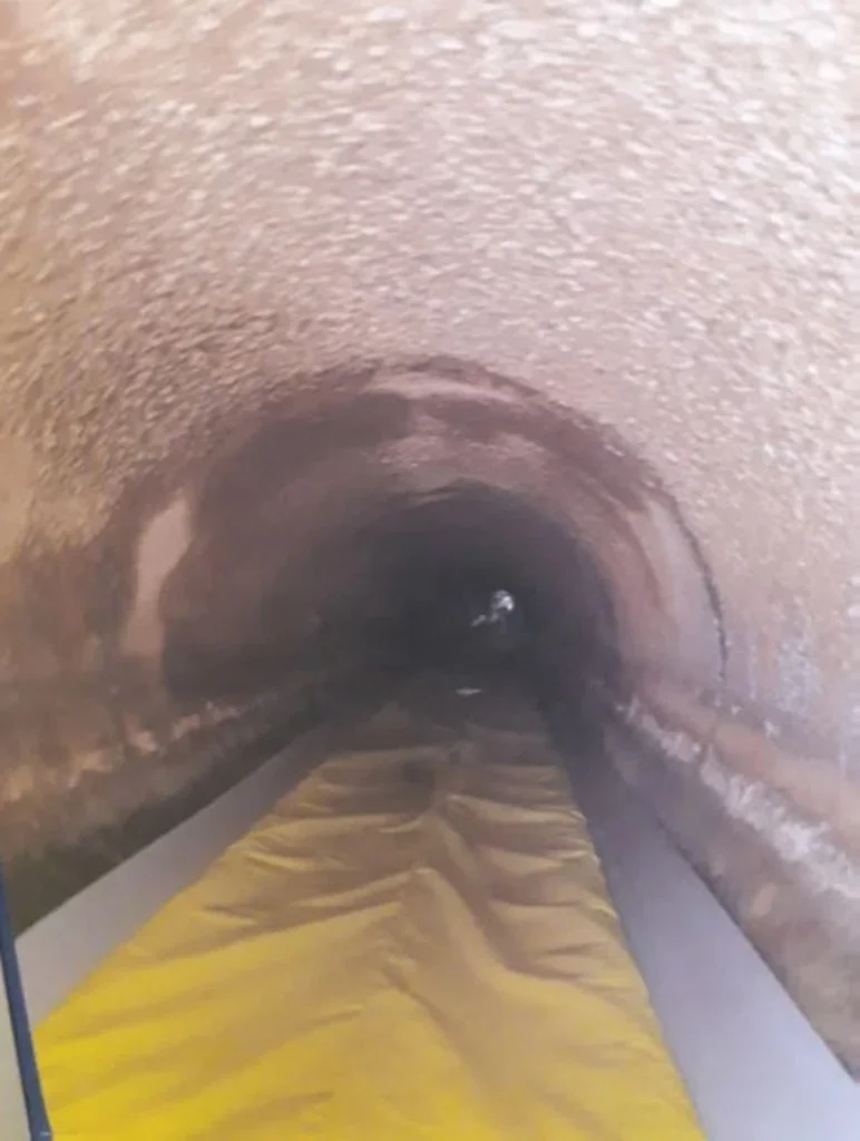
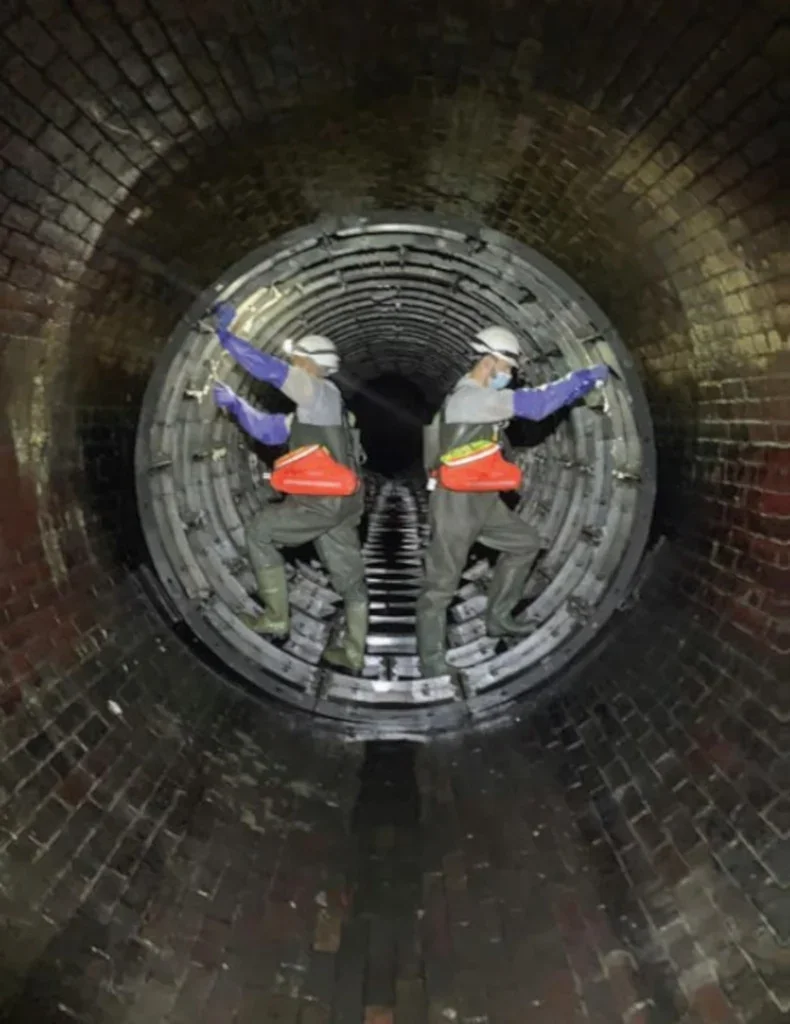
At Whitlingham, an 11m-deep, 1676mm-diameter brick sewer had been attacked by H2S, causing bricks to become dislodged.
Before work could begin, innovative CCTV technology was used to provide a full 360º sonar and laser scan profile of the sewer. The survey found the sewer was up to 45% full of debris, with over 135m3 requiring removal. A steel shield was installed ahead of the GRP pipes providing a safe area for the workforce to remove the debris whilst simultaneously pipejacking without being put at risk of a potential collapse.
To carry out the works, 750m of temporary 1000mmdiameter steel overland pipes was used along with a temporary pumping station monitored continuously, to overpump the existing sewage flow with two 5.5mhigh ‘Pipe Bridges’ installed over a public right of way and Anglian Water access road to minimise disruption.
To prevent any interruption to customer facilities, the overpumping was installed and commissioned overnight during a short shutdown of the Norwich catchment and utilised a bespoke prefabricated dual manhole. To protect the workforce working downstream, three penstocks were used to control the flow out of the sewer.
Given some of the major infrastructure projects underway in the UK, we are regularly presented with challenges to ensure that existing assets are either able to be integrated into newer systems or protected through the construction phase.
In London, at Thames Tideway Tunnel’s Blackfriars Bridge Foreshore site, we were required to install a flume inside the existing Victorian LowLevel Sewer within the Thames River Wall. The pipe was made up of 41 rings of 10 individual steel segments and it carried the flow of the sewer during construction works and later allowed breakthrough to connect the sewer to the Thames Tideway Tunnel.
Central London locations like this present difficulties beyond working inside the harsh and restrictive live environment of the existing Victorian sewer. In particular, logistics can be challenging – the restrictions of tides and night time working meant that we were limited to tight threehour working periods.
By contrast, our work at the Middle Level Two (ML2) Sewer required us to install a 75m length of nonstructural liner to protect the 2mdiameter Victorian structure from construction works associated with High Speed Rail 2 (HS2).
Access to install the liner was provided by two shafts one existing and one new. The latter was constructed at a point where the route of HS2 was in closest proximity to the sewer to optimise monitoring. The shaft was constructed as a caisson but installed using underpinning from the collar rather than by jacking so avoiding pressure on the 19th Century, brickconstructed sewer.
ELAN VALLEY AQUEDUCT
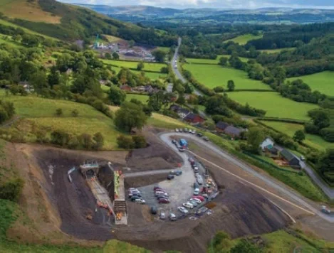
The Elan Valley Aqueduct (EVA) is a Victorian culvert which, for the past 100 years, has supplied water from mid-Wales to Birmingham. Deterioration of the original structure meant that replacement of the conduit was required in three locations – Bleddfa, Nantmel and Ffrydd Wood (Knighton).
The techniques used in the original Victorian construction of the EVA include mined tunnels, open-cut conduits and inverted syphon pipework. It is a 2.4m x 2.8m inverted U-shape, advanced primarily with timber heading and lined with concrete, filled behind permanent brick formwork.
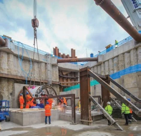
The replacements consisted of 3.05m-internal diameter segmentally lined tunnels, located adjacent to the existing aqueduct. Installed offline, each section is more than 1km in length.
Innovation delivered valuable savings in the shape if rationalising the TBM launch connection structures into a single secant piled cofferdam capable of accommodating both requirements – an approach that was echoed at our recent sewer diversion work at The Greenway in Ruislip. The approach saved programme time and reduced the required working area and earthworks.
A critical phase of the project was connecting the new tunnels and turning flows at the connection points. The hydraulic design required minimal frictional losses through the change in the cross section to the new circular tunnel from the rectangular aqueduct. The transition sections therefore required a gradually varying cross section from one shape to another. This was achieved through a modular precast concrete system for the base and walls. ‘Special’ sections were then lowered into the aqueduct to turn flows into the new tunnel. The channels were finished with precast concrete roof sections bolted into the top of the precast walls.
A key benefit was that the civils works for the connections could be achieved within a three day outage – eliminating the possibility of a drinking water shortage in Birmingham. Clever modular construction meant the elements were manufactured off site and dropped into the channel when required during the outage.
Our success at the EVA will ensure that Birmingham and the surrounding areas has a resilient water supply for years to come.
It has been calculated that the UK’s active water infrastructure extends to more than 300,000 km of buried pipes, some of which date to Georgian times. As the population grows and climate change presents greater impacts, the requirements for its effective maintenance and remediation will only grow.


