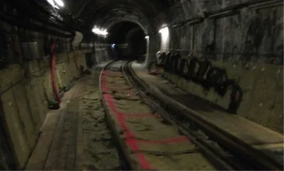
INTRODUCTION
In the first BTS evening meeting of 2024, Christian Gilbert presented a lecture ‘Artificial Ground Freezing (AGF) – Water Tightness and Temporary Soil Structure.’ The lecture explored the complexities and innovative solutions associated with artificial ground freezing.
The presentation introduced the AGF process, identified key constraints on use of the technique and then followed up on the theoretical concepts with some practical examples, with particular focus on the work carried out on Metro Line 14 Clichy Saint-Ouen in Paris, alongside a project undertaken in North Africa, subject to an extremely high salinity environment.
AGF is rarely used, because of its relatively high complexity and cost, but when other techniques, such as jet grouting, soil mixing or shoring, won’t work in saturated soils, engineers are forced to consider it.
In simple terms, artificial ground freezing involves installing pipes in the ground and passing very cold liquid – either brine (a saline solution) or liquid nitrogen – through them, extracting heat from the ground so that temperature of the material around the pipes lowers and the interstitial water freezes, creating an impermeable barrier and expelling the heat through refrigerant units. The AGF process works in a closed system, meaning none of the liquid transfer medium comes into contact with the ground itself.
As well as making the area watertight, AGF works to increase the strength of the soil temporarily so that excavation can be carried out safely and a permanent structure installed. Historical usage was centred around mining, however it has many applications and is now commonly used in tunnelling for infrastructure projects. For example, it could be used to sink a shaft or to excavate short cross passages that are to connect parallel large-diameter tunnels, for instance on a city’s new metro project.
AGF is not an off-the-shelf solution.
It is important to understand the principles behind AGF so that early design decisions can be taken to ensure the correct methodology is implemented, and then, later, so that adjustments can be made on site through observations of ground response to the freezing process and the stresses applied during construction.
AGF PRINCIPLES: MECHANICAL PROPERTIES & METHODOLOGY
To properly establish whether AGF will work for a particular project, it’s important to understand how different soils behave when frozen, the impact of different levels of water saturation, the groundwater flow conditions, and whether brine, nitrogen – or both – would be the best form of refrigerant.
The strength of the frozen ground varies depending on the soil type, with the unconfined compressive strength (UCS) decreasing as the particle size of the soil decreases, when operating at temperatures able to be achieved in an engineering context. Temperature dependence of UCS for several frozen soils and ice is explored by Sayles (Sayles, 1966).
Degree of saturation of the soils must also be considered. A minimum percentage of soil saturation is required to ensure the freezing process has sufficient water available to take hold and provide an adequate thickness of frozen ground. UCS ratio as a function of the degree of saturation at T = -10°C was the work done by the International Symposium On Ground Freezing Working Group No2 (1992).
In addition to soil types and the level of saturation at any given site, the capabilities of soils subject to AGF are heavily dependent on their reaction to creep, meaning that after a material has been loaded at a constant level for a long period, it can fail suddenly, at a lower stress than its UCS would suggest. This must be tested for and then factored in during calculations for AGF so that the critical strain at which creep begins is not reached, since the frozen ground may have to support an open excavation for several months.
Uniaxial creep tests on saturated medium sands at -10°C to establish baseline strain and strain rate against time were carried out by W. Orth in ‘A Creep Formula for Practical Application Based on Crystal Mechanics’ in the 5th International Symposium On Ground Freezing (1988).
Groundwater conditions also play a key role in AGF, as the specific latent heat requirements for water to phase change from a liquid to a solid represent the majority of energy required in the ground freezing process. This has impacts on the viability of AGF because if the groundwater flow rates are too high then the water will not be in contact with the freezing pipes long enough to change phase from liquid to solid.
Groundwater is a governing factor when determining the most appropriate freezing method, using either brine or nitrogen as a refrigerant medium. Liquid nitrogen operates at much lower temperatures than brine, therefore it freezes the ground over a shorter period of time and can accommodate higher groundwater flow rates (see Table 1), however it is much more costly to run as the energy required is significantly higher. If groundwater flows are too high for liquid nitrogen alone, ground treatment techniques such as jet grouting can be applied to limit the groundwater’s velocity and make the required state change possible.
The volumetric change of the soil as it freezes must be considered, as the frost heave can impact any surrounding assets. The volume of the soil particles themselves will remain constant, however as water freezes, its volume increasing by approximately 9%.
A soil’s susceptibility to frost heave is directly related to its permeability and its capillarity.

Highly plastic clays have high capillarity, however their very low permeability means that the quantity of water available to form ice lenses is limited.
On the other end of the capillarity-permeability spectrum, sands and gravels, with little to no fines content, have a high permeability due to their large pore sizes, however their low capillarity, means that the suction of groundwater to the freezing front is limited.
Soils falling between high permeability/low capillarity and high capillarity/low permeability, such as silty soils, have a much higher susceptibility to frost heave. The American Concrete Pavement Association (ACPA) has provided guidance on the susceptibility of various soil types to frost action as functions of capillary action and permeability, in 2008.
PRACTICAL CONSIDERATIONS AND CASE STUDIES
AGF is a technique that embraces the observational method. Any design and construction methodology involving AGF is supplemented by, and reliant on, instrumentation and monitoring to ensure agile and adaptable responses to any changes in conditions, which must be accounted for and accommodated.
Paris Metro Line 14
The first case study presented in the lecture was the use of AGF on Paris Metro Line 14 – Porte de Clichy, where the method was used to support the excavation of the metro line extension, whilst temporarily exposing the underside of the existing Metro Line 13 tunnel situated directly above.
The excavation was carried out within the Beauchamp Sand, which is overlain by Saint Ouen Limestone and sits approximately 18m below existing groundwater levels. Due to the highly permeable fine sands, it created a difficult environment to freeze.
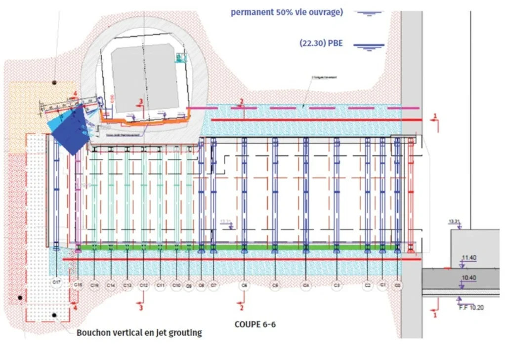
In order to achieve the desired effects of creating an impermeable barrier, jet grouting was used to form a ‘plug’. The process involved horizontally installing 24 freeze pipes from the station shaft through to the jet grout plug.
There were an additional 11 freeze pipes installed from the metro line above. The circuit containing the brine solution was completed via boreholes down through the lining of Line 13.
North Africa
The second case study was a project in North Africa, where AGF was being implemented to excavate the 20m-long cross passages between two 15m-i.d. main tunnels. The surrounding geology consisted of a very fine sand and the project was subject to a 50m head of water with a high saline content.
The key challenges in this case were the region’s high temperatures and the presence of the highly saline water. The freezing point of water lowers with increased salinity, making the freezing process more difficult. Testing for appropriate UCS values to meet strain criteria was carried out extensively, providing data that showed the ground would require freezing to temperatures of at least -15°C in order to be able to provide sufficient strength for the duration of the construction work.
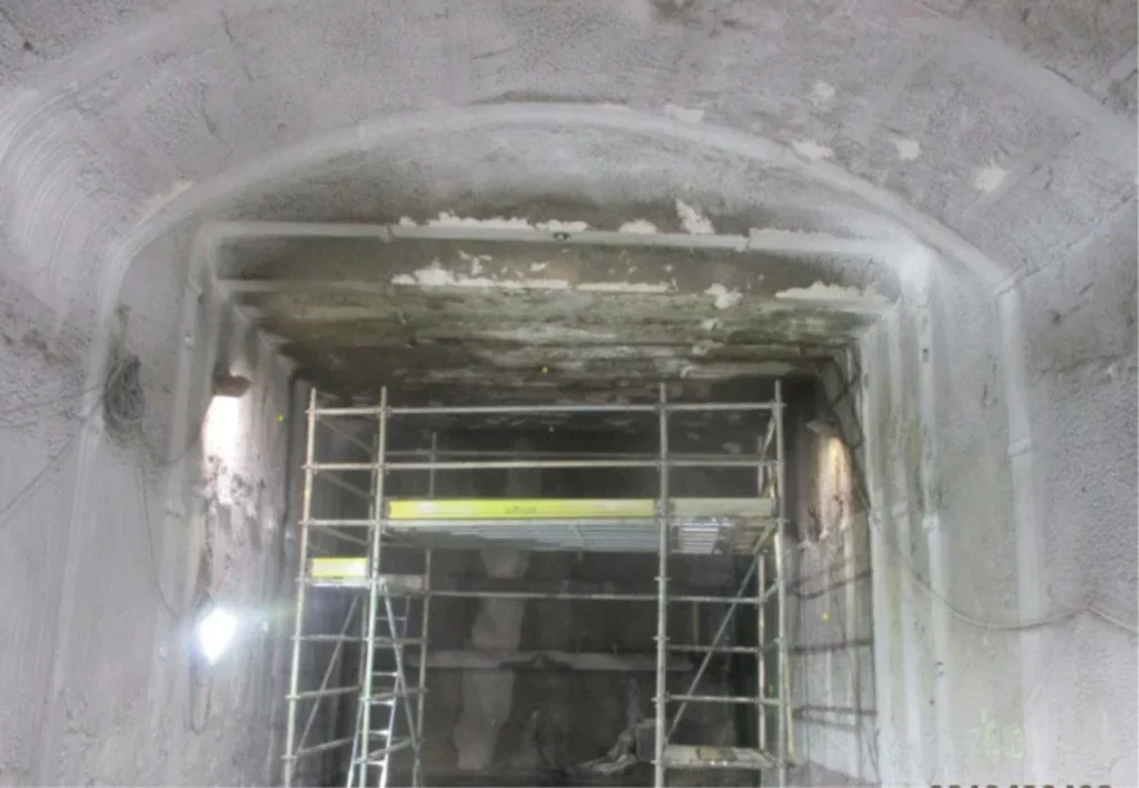
There was more added difficulty coming from the water pressure and the presence of an active pumping well in close proximity to the location of the proposed cross passage. Nearby pumping is detrimental to the freezing process by increasing groundwater velocity, making the state change from liquid to solid difficult to achieve. . To counter these issues, a refrigeration unit was installed in the cross passage, and temperatures were meticulously monitored throughout the tunnel excavation process.
Despite these efforts, due to the tight tolerances involved when drilling from one tunnel to the grout surround of the other, achieving full contact between the tunnel and the impermeable frozen ground was problematic due to water flow and imperfect grouting. Consequently, the team reinforced the freezing effort in the problematic areas using additional freezing pipes, overcoming the challenging conditions and managing to create a frozen body with a UCS of 1 MPa, which was suitable for the cross passage excavation.
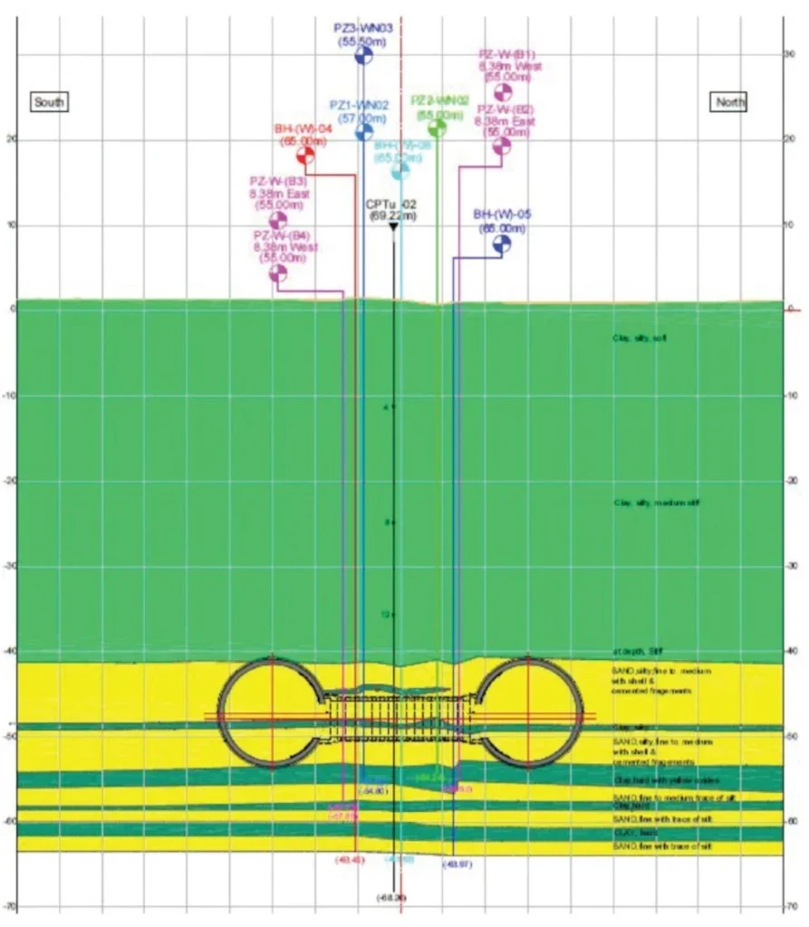
Instrumentation and back calculations played a crucial role in diagnosing and addressing these challenges. They helped to monitor the groundwater flow and to establish the areas where there was insufficient coverage of freezing pipes due to the variation between proposed freezing pipe locations and their actual installed locations.
The highly saline environment lead to issues during construction, as the ground began to freeze. Heat would propagate slowly, meaning that during the change in state from water to ice, the salts within the water would be expelled into the surrounding unfrozen water, which would in turn increase that water’s salinity and lower its freezing point yet further. On the project, there were pockets of liquid water with a temperature of -19°C being found between the two rings of freezing pipes and being extracted during construction.
PARIS METRO LINE 14: CLICHY SAINT-OUEN STATION
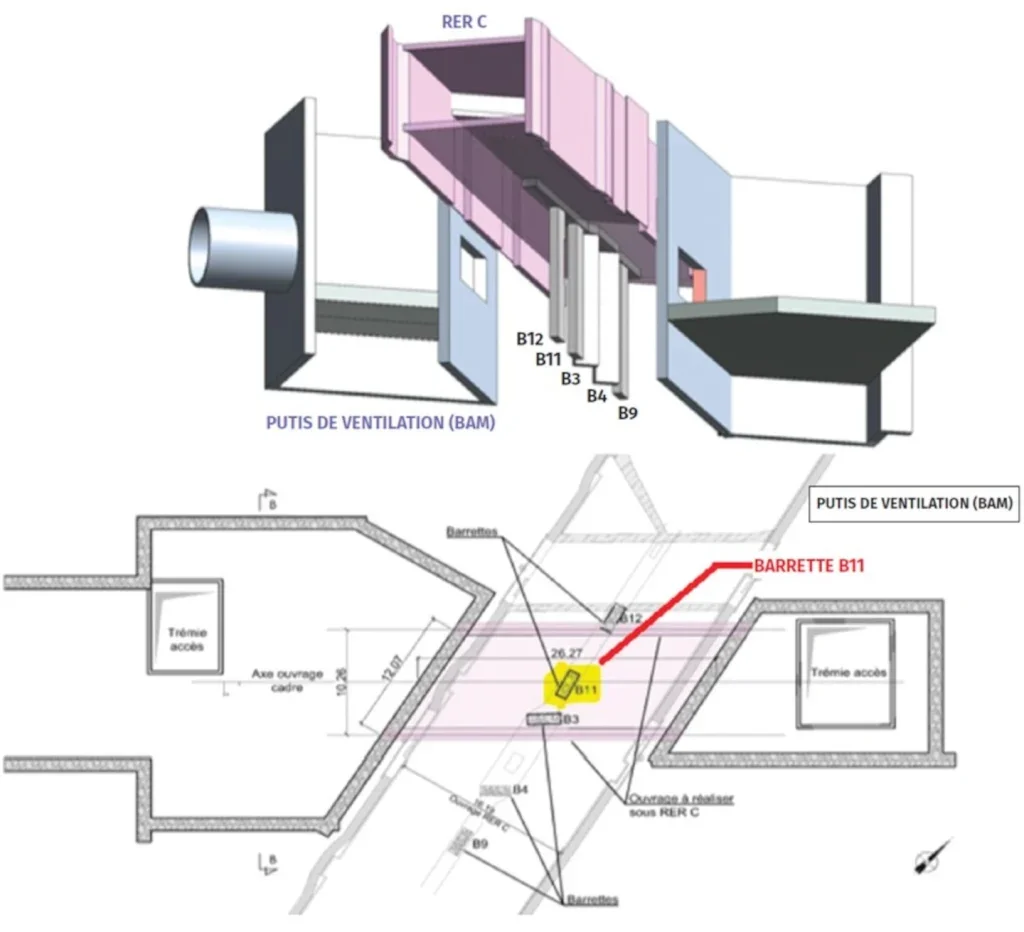
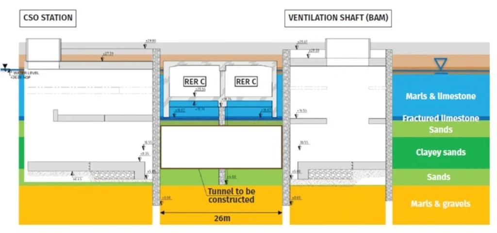
The main case study presented in the lecture was that of Paris Metro Line 14’s Clichy Saint-Ouen station, where the new extension will pass directly underneath the existing cut and cover tunnel that was built in 1985, with barrette foundations. In the new tunnel project, barrette B11 was to be cut and the load transferred onto the new box; there was a cross section reduction on barrette B12; and, barrette B3 was to be incorporated within the new tunnel with no transfer of friction, allowing the two boxes to move independently.
The soil in the area was characterised by very fine sand, clay, and sand, exhibiting poor strength and creep behaviour. It was initially considered that completing grouting below the existing slab could create a watertight environment, but this approach proved difficult to implement due to the close proximity of the existing tunnel, above; any excessive heave would impact the running of the metro line overhead. So, jet grouting was used as a supplementary method of groundwater control within the marls and limestone above, and in the marls and gravels below, as a way to assist with uplift stability.
No laboratory tests were performed but values were chosen in accordance with tests performed for a similar project close by, as any ground investigation at the site was impractical. The mechanical properties were chosen using particle size distribution as per the work done by the International Symposium On Ground Freezing Working Group No2 – Testing methods in frozen soils, (Beijing 1991).
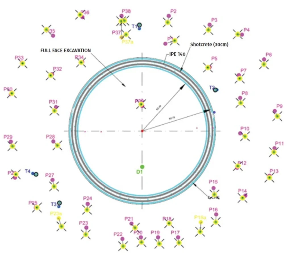
In response, the team developed an alternative solution using AGF in the shape of inverted vault arches. The freezing process involved placing freeze pipes at 0.65m centres to varying depths and ensuring a minimum thickness of 800mm for adequate temperature control and water tightness. Although a more aggressive approach of lowering the temperature to -20°C was considered, stability for uplift was prioritised, as any excessive movement to the tunnel above would have an impact on the running of the metro service. The final freezing pipe arrangement required a total of 1709 linear metres of drilling, there were 122 freeze pipes (61 per side) averaging 14m in length.
The arrangement of the freezing pipes utilised an invert vaulted arch, this is because of the impact of uplift; by using this shape, the uplift pressure imparted on the underside of the arch is distributed to the frozen walls.
Keeping the frozen body in compression is imperative as the stresses within the frozen body must be compatible with the mechanical properties of frozen sands.
The excavation sequence was adapted to cater for uplift issues.
The freezing methodology was to carry out the initial freezing of the U-shaped section using liquid nitrogen for five days to ensure freezing within the very permeable limestone, then switch the cryogenic fluid to brine for two weeks to maintain the frozen body.
The central vault was then frozen using liquid nitrogen over two days, before again this section was switched to brine to maintain the frozen body of the central vaulted section.
Continuous temperature monitoring, as a method of ensuring UCS values and strain rates, was essential to maintaining stability during the freezing process, it also allowed for an efficient use of refrigeration equipment, whilst ensuring the movements were limited to acceptable levels. The monitoring utilised 30 thermocouples. Sensors were placed every 2m along the tunnel, requiring 450m of additional drilling.
For each sensor, two threshold values were defined as a means to ensure water tightness:
- Orange alert threshold: -2°C, at 0.75m from freeze pipe
- Red alarm threshold -2°C, at 0.65m from the freeze pipe
If temperature exceeded either threshold then SMS and email alerts were automatically sent to pre-selected project personnel.
Unexpected issues on this project included: heave causing upward movement of the line above the excavation in the second month of the works; warming of the north wall in the ninth month of the works; and, further heave causing more upward movement in the tenth month. The use of observational methods allowed for adaption of the temporary works as these problem arose, emphasising their critical part in making AGF an effective solution.
In order to mitigate the heave incurred by freezing of the central vault, a series of steps were taken, including: raising the brine temperature, to no effect; stopping the brine flow completely, also to no effect; and, then, finally actively circulating 15°C brine to induce active melting, which led to a stabilisation of the situation and prevented further heave occurring.
The north wall began to melt, the temperature rising to exceed the ‘Orange’ alert level. Probable causes were identified as likely to be air convection, heat of hydration of shotcrete, and lights used to illuminate the construction workings.
The section loss occurred in a section of the tunnel that was known to be sensitive, due to the water circulation within the surrounding geology (limestone) and the proximity of the neighbouring shaft. To prevent further section loss, the cryogenic fluid was switched back to liquid nitrogen, which was then maintained via a ‘stop & go’ approach, which meant temperatures had to be monitored closely to ensure they neither got too low, risking heave, nor too high, risking frozen body section loss.
After a few weeks of the ‘stop & go’ system, by the tenth month of the works the ice had reached the invert of the line above. Further heave occurred, causing upward displacements to the line. The method implemented to limit this heave was to amend where the inner pipe terminated within the outer pipe, as the terminus of the inner pipe tends to be the location of lowest temperature.
By amending the location of the inner pipe terminus, the location where freezing was centred was changed, leading to cessation of the heave.
The final steps of the project were to expose the 3No. barrettes supporting the existing line and carry out the amendments to them to allow for the construction of the new tunnel beneath. To enable these works on the barrettes supporting the old tunnel, the roof of the new tunnel had to be supported off the walls on jacks. The jacking supports were continually adjusted in line with monitoring data, allowing for redistribution of stresses between the barrettes as needed.
After the construction of the new tunnel, active thawing was induced by circulating warm brine, for three months, in a specific sequence to allow for minimal impact to the surrounding assets. The thawing sequence was: firstly, to open the inverted vault at the bottom to apply water pressure to the tunnel; thaw the walls from top to bottom and allow for a chimney to form; and, evacuate melted water and for the soil grains to rearrange where heave had occurred. This was followed by a six-month long monitoring period of the beam and line above.
CONCLUSION
AGF is a powerful method when complex hydrogeological context requires its use. It has a large reliance on the observational method, which is relatively rare in civil engineering. Its successful use depends on a good monitoring regime, good levels of engineering competence, and also experience, so that theoretical calculations can be compared with the reality of execution.
The method can be an effective and safe way to excavate below ground in saturated sands or silts. But those who implement the technique must expect the unexpected, be prepared to work out what is happening and to be reacting dynamically as the situation requires.
QUESTIONS AND ANSWERS
After the lecture, held at ICE in London, Christian took questions from the floor.
Some questions considered technical aspects of the AGF works, such as what may change in the structure of a soil as a result of using the technique, to particular salinities involved in some works.
The principal discussion, though, considered the case studies as a way to enquire about contractual situations, especially where there can be a close interface between temporary and permanent works design.
The response was that, in this case, the contractor had proposed a solution and so took measured risk in doing so, but there was also responsibility kept by consultant – in that to be approving, or not, the intended actions at various particular situations of the works as they proceeded and proposals arose. The view taken by the consultant, to say yes or no to what was sought, also depends on the measured level of risk involved in each instance – in this case, such as some grouting issues under a slab were considered to be low risk. In that light and with difference in view between contractor and consultant, then, the latter decided to see if the former was right. But, he noted, there is risk for consultant and owner.


