INTRODUCTION
Being both well written and structured, yet perhaps shorter than anticipated – at only 16-pages in length, cover to cover – the ITA’s guidance on rock classification for ground support on open-type TBM bored tunnels comes sufficiently well illustrated, with graphics, tables and references. Given such brevity it usefully skips on a Contents page and gets straight down to practical briefing in five chapters and wraps with a short conclusion.
Although A4, and likely to be a digital reference copy rather than paper, given it would be quite thin, the report gives the sense of easily being a well-thumbed reference.
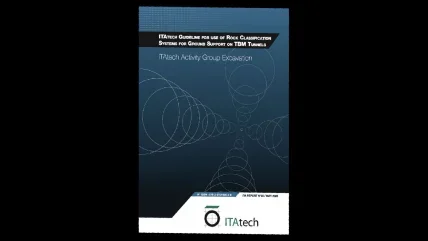
Formally, the report is ITA’s Report No30, published mid-2023, and comes from ITAtech Activity Group Excavation. Its official title is ‘ITAtech Guidelines for the use of Rock Classification Systems for Ground Support on TBM Tunnels’.
TBM TUNNELLING CHALLENGE
While rock classification systems have been developed over many decades, helping tunnellers to move ground support choices beyond isolated case-by-case decisionmaking about what to do, in what way and by how much, a challenge remained, for TBM tunnelling.
The report says that: ‘When these systems are applied to rock support in mechanised tunnelling it becomes a problem that the empirical data is obtained almost exclusively from the drill and blast tunnelling method.”
Challenges arising are the rock support is not then optimised for TBM tunnelling, and doesn’t account for the rock not being blast damaged but “relatively smooth”.
To address the challenges, the report puts forward a modified rock support selection methodology. The proposed alternative system, adapted to bored tunnels, draws upon published literature of both of the following established rock classification systems – Q (Barton, Lien, & Lunde, 1974) and RMR (Bieniawski, 1989), respectively. The report notes that, additionally, the adaptions are “aligned with the authors’ experience.”
The report says that the modified system “is suitable for use in design, cost estimating, and other rock support considerations” in relation to open-type TBM tunnelling, focused on the areas immediately behind the cutterhead (L1 area) and the remainder of the machine (L2). But the proposed rock support schemes are not a guide for the needs of final lining, it adds – for such is likely to be determined prior to excavation.
The TBM back-up area and farther back still are classed as L3 areas, and as such are not covered by the proposed modified rock support scheme, which is focused on the needs of the L1 and L2 areas, respectively – L1 requiring more than L2.
The report notes improvements by TBM manufacturers and industry for installing temporary rock support. That being so, it highlights that temporary ground support in given rock mass classes in such TBM tunnels can be reduced, further noting this is especially important where support quantities are limited and can be installed simultaneously with boring activities.
THE APPROACH
The report explains the rock support methodology being pursued are based on stability and safety requirement for different scenarios, and takes the Q-method as a basis, including its Excavation Support Ratio (ESR) approach. The ESR values in the report’s diagrams generally have a correlation with those that Barton suggests for TBM tunnels, it adds.
The report then discusses unlined TBM tunnels having far less installed rock support compared to drill and blast method (based on literature and author experience), and that for TBM tunnelling in jointed and faulted rock this reduction is “especially relevant” in some rock classes, and adjustments are required.
The methodology chapter then concludes with a short discussion on the correlation of the Q and RMR systems.
Next, the following chapter discusses rock support diagrams, noting that the guide presents two – for temporary rock support, and for moderately long-term use without secondary lining, respectively. Diagrams then given come from adapting the Q-diagrams and suggested adjustments (Barton & Grimstad, 2024) – but unlike the former do not use a logarithmic scale for the y-axis, and use a set of ESR per diagram.
The report says: “This change was made so that the curves can be read directly based on the TBM diameter.”
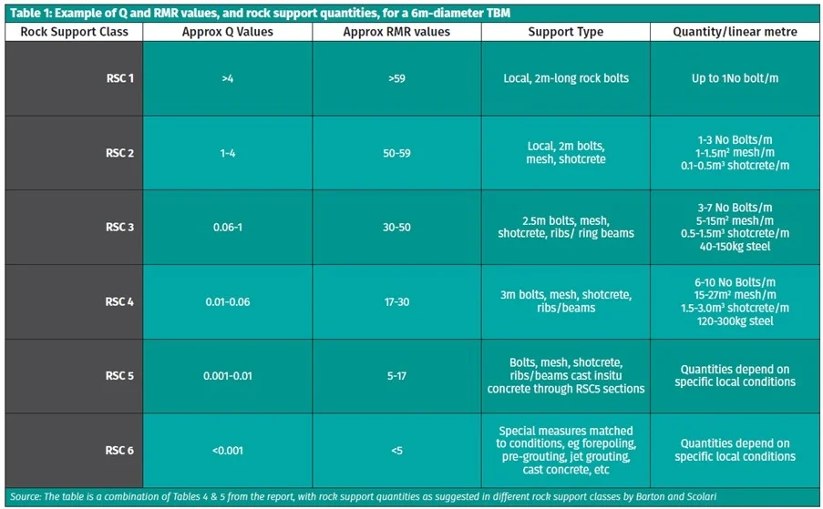
The rock support diagrams produced have six Rock Support Classes (RSC), which are each briefed, and then examples of rock support quantities discussed. Two tables are given, which in this article are combined and presented here.
The report on the modified rock support methodology also presents some special considerations for more challenging TBM drives, such as rock stress induced problems like squeezing and rock bursting, and high pressure groundwater inflows.
These special geological considerations are discussed in the following chapter in four information-packed pages, including two large and detailed tables, dealing with the stress and inflow issues, respectively. In the former, challenges are emphasised at weak zones, including those with clay or chemically-altered rock mass, but also competent rock with high stress and burst risk; and, on the latter, discussion noted the importance of probe-drilling, pre-excavation grouting (PEG) and potential for some use of segmental lining.

CONCLUSION
At the end, the ITAtech report says it is a guideline that presents a model that uses empirical data and conclusions from literature to do two things with respect to rock support: to suggest better methodology and also quantities to use, respectively, when undertaking a TBM drive.


