The steep, winding climb of the National Highway through the Adelaide hills had been a cause of concern for some time. On average there were 200 accidents a year, some fatal, and all causing significant delays to traffic.
An upgrade of Mount Barker Road had been on the agenda for more than 12 years when, in early 1997, the then Highways Department (now Transport SA) called for tenders to construct the Adelaide-Crafers highway. The A$151M ($87.5M) project, fully funded by the Federal Government, was part of the National Highways Programme, and was designed to provide a new and safer alignment through the Adelaide Hills.
The project consisted of the construction of some 8.3km of dual three-lane highway involving extensive earthworks. Key elements included:
– Tunnels: two parallel tunnels 15m wide, 8m high, and 480m long.
– Earthworks: 2.1M.m3 of rock and soil to be moved – 80% to be used in fill areas, and the remainder to rehabilitate an abandoned quarry.
– Bridgeworks: Mount Osmund interchange, allowing safe access to the highway in both directions.
Measdays interchange, three-span, cast in-situ box girder bridge 99m long. Devils Elbow Interchange, a single-span underpass.
The Macmahon Walter Construction joint venture was formed early in 1977 and called in engineers Connell Wagner to provide expertise for the tunnelling aspects of the project. The joint venture won the tender with an alternative design, central to which was the replacement of cut-and-cover tunnel sections with in-situ driven tunnels. Work began on site late that year with the first tunnel breakthrough coming in August 1998.
High-fracture ratio
Ground conditions in the area of the tunnels consisted of slightly weathered, high-strength slates and very high-strength quatzites. Numerous shearzones, steeply dipping slate cleavages and the high-fracture ratio resulted in frequent stability problems.
One immediate benefit of replacing the original cut-and-cover tunnel design by a driven tunnel was a reduction in the amount of excavated material to be dealt with. Altogether, it is calculated that some 75,000m3 of excavation was done away with. However, since all material had to be hauled along public roads, the joint venture was anxious for the earliest possible breakthrough for one tunnel so that it could form part of the haul route. A further problem was the lack of cover at the portal location.
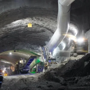
In order to speed tunnel excavation, Connell Wagner devised a temporary support system which could be followed by the permanent lining. The elements forming the support system included temporary rockbolts and a thin shotcrete shell which supported the tunnel during construction and through the period when it was being used as a haul route. Additional strengthening with canopy tubes and steel ribs was used to establish the tunnel portals in the highly weathered rock. This was followed by a permanent concrete lining.
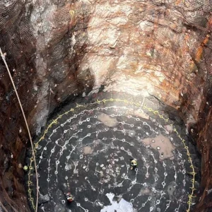
To provide support at the portals, a fan of 165mm diameter pipes was installed above the portal to form a canopy, which itself was supported by reinforced concrete portal slabs. Excavation was carried out using a high-capacity hydraulic hammer with a roadheader used to trim the perimeter of the tunnel profile. This allowed the bulk excavation of the tunnel face without the risk of overbreak and extensive support work.
Increased excavation rate
|
“The proposed lining was designed with a sacrificial concrete thickness which would allow concrete spalling of some 80mm during a fire and still retain a residual strength of around 80%.” |
The effect of blasting could have been to open up the jointed rock mass, possibly destabilising the tunnel crown. The use of the hammer also meant an increased excavation rate and the combination of methods resulted in a very close excavation profile with subsequent savings on concrete lining costs.
The design and construction of pipe canopies to overcome difficult ground conditions and/or to establish portal openings in soft ground relies heavily upon the coupling of the canopy tubes, steel ribs and soil. Difficulties arise from the inherent misalignment of the steel tubes and problems in installing the stiff steel rib tunnel supports.
European practice is to use steel ribs with a ‘top hat’ profile, which allows them to be slid into place. However cost, and the difficulties in sourcing this type of rib caused Connell Wagner to investigate an alternative solution. The choice fell on railway steel sleeper profiles, rolled to the correct tunnel profile – a decision which proved to have several advantages.
Length expansion
The potential of the steel rib for ‘nesting’ [stacking] allowed it to expand in length, and thus made it easy to support the fanned canopy tube arrangement.
The cross-sectional properties comfortably supported the expected ground loads.
The flexural capacity of the steel ribs allowed them to adapt easily to nominal variations in the excavation profile and to provide closer support to canopy tubes which were out of alignment.
The profile cross-section favoured the application of shotcrete and ensured excellent contact between the rock and the steel sections.
For the permanent lining Connell Wagner worked with its associate company, Mott McDonald, to develop a lining support which would maintain its structural integrity during a fire incident. The team drew on intensive research carried out after a number of events, including the Channel Tunnel and Storebaelt fires, plus tests carried out under the Eureka EU Firetun project.
The proposed lining was designed with a sacrificial concrete thickness which would allow concrete spalling of some 80mm during a fire and still retain a residual strength of around 80%. This would permit subsequent entry to the tunnel under safe conditions and, following removal of any affected concrete, repairs could be undertaken. This variation to the client’s original design was accepted and the lining was installed using travelling formwork.
One aspect of the contract which was highly unusual for Australia was that decision making with regard to the ground support regime was largely carried out off-site, with the designers in Sydney and the contractors head office in Melbourne liaising with the site.
This was possible because the designers had developed detailed ground support rules. These were supported by daily mapping of the tunnel face by the project geotechnical engineer. The mapping sheets and monitoring information, including digital images of the tunnel face, were sent electronically to the designers so that the ground support regime could be approved. Regular follow-up inspections were carried out, and designer and contractor retained a close working relationship at all times.
Not having to set up a full design presence on site was inevitably a considerable cost saving. And the fact that the project was completed on budget and ahead of schedule is a tribute to the effectiveness of both design and working methods.