The three tunnels described in this article form part of the west section of the Rodoanel Mario Covas, an express ringroad around the Metropolitan Area of São Paulo. Situated in Brazil’s south-east, São Paulo’s Metropolitan Area is the country’s most important, having a population of about 18M – 10.5% of the country’ population – and producing 17% of the Gross National Product.
Currently the urban transit system is completely saturated, daily more than 100,000 trucks enter and leave the Metropolitan Area of São Paulo through the ten highways that cross the city. Five million registered cars also contribute to a chaotic situation. The resulting traffic jams produce pollution, fuel wastage (about 1.5bn litres per year) and an immense loss of working time (about 1.1bn hours per year)
Rodoanel’s construction was started in 1999 on the high priority 32km long Western Section. This has been in operation since October 2002 and is regarded as vital as it interconnects five of the 10 highways that converge on São Paulo.
When the whole project is completed, Rodoanel will be 170km long and will form an elliptical shaped ring around São Paulo’s metropolitan area, between 20 and 40km from the city centre (Figure 1). The project’s three twin tunnels, with each tube 20m apart, constitute the largest cross sections ever built in Brazil (Table 1). Tunnel 3, due to its length, has three cross-passages, used for access during construction and now as safety passages during operation.
Works for the Western Section were constructed under lump sum contracts, based on work schedule multiplied by unit prices, providing the criteria for minimum final price. The total costs of the tunnels 1, 2 and 3 were in the order of US$18.5M, US$45.5M and US$55.6M respectively, with monies paid by monthly valuations of actual performed work. Project financing was shared by State and Federal Governments, in a 30/70% proportion.
Geology and construction method
The hard rock encountered during excavation of the tunnels consisted of metamorphic rocks with metamorphism grades varying from low to high. Tunnel 1 runs through magmatized gneiss and magmatites with a rock mass class (Barton 1974) of Class A (Q = 98) to Class F (Q = 0.042) and an average Class A/D (Q between 32 and 3). Tunnel 2 progresses through Class D (Q = 2) to Class G (Q = 0.002) phyllites. Tunnel 3’s alignment is through metasandstone and metaconglomerates from Class E (Q = 0.33) to Class B (Q = 18).
Due to its longer length, Tunnel 3 is the most important on the West Section. Therefore, this article will refer to Tunnel 3, from now on.
The construction method chosen was NATM (New Austrian Tunnelling Method), which has been adopted for the majority of Brazilian tunnels, due mainly to the typical geological, financing, labour supply and contractual characteristics prevailing in the country. For the central section of the tunnels, the cross section excavation was divided into top heading and bench and was excavated in the following phases: central gallery and lateral enlargements to complete crown excavation and full section excavation (Figure 2).
For the portal sections, sequentially excavated in soil and decomposed rock, temporary support was provided by lattice girders and steel fibre reinforced shotcrete. For the central section of the tunnel, in rock, primary support consisted of 25mm diameter steel anchors, 4m long, with the anchor length fixed with fast setting resin and the rest fixed with slow setting resin. This was followed by the application of shotcrete with steel fibres (anchorage patterns are shown in Table 2). Second phase lining for both soil and rock sections was also steel fibre reinforced shotcrete.
Some ancillary support measures, to stabilise the rock in critical areas, especially in the portals, were also used. At least three sets of forepoling, consisting of grouted steel bars were placed in the crown contour. In the North Portal, where ground water level was high, the water table was reduced using long horizontal gravity drains.
Dimensioning of temporary supports
Initially, several analyses by the ‘rock relaxation’ method were made using the FLAC software, considering it to be a continuum and introducing several relaxation phases that could be caused by the excavation sequences. Following this, an analysis of incremental excavation was made, using the UDEC program which considered the rock anisotropy and the grouping of faults. Finally checks were made on the tensions and displacements in each construction phase, in the lining and the rock mass.
Results showed that the proposed construction method gave ‘factors of safety’ compatible to accommodate the variability of the geotechnical parameters expected in the rock mass, in all construction phases. Based on these results and comparing the actual measurements made, it was possible to verify the performance of the construction method in each phase.
Externally installed instruments, like surface level points, deep extensometers and piezometers as well as instruments internally installed, such as convergence meters and displacement pins, recorded normal stabilisation times and produced results consistently lower than those expected from the simulations.
Dimensioning of final lining
Major design considerations included the thickness of the first and second phase lining. The first 50mm of the first phase lining was ignored due to the poor control of the shotcrete layer. Temporary supports such as lattice girders and steel rock bolts that only had a structural function during construction, were disregarded.
The final lining was checked using typical ground parameters to balance the adopted potential loading in order to meet standard design safety factors (Table 3).
Water inflow during construction
Before constructing the 2nd phase lining, precautions were taken to control water inflow into the tunnel vault. Several types of treatment were adopted for the various inflows experienced. To combat the occurrence of moisture spots the contractor created weep holes and kept the option to build mini channel drains for the more severe cases. Occasional discontinuous flow points were treated in a similar fashion, although the mini channel drains were a necessity not an option. For the control of continuous flow points and the more serious concentrated jet flows, drilling and grouting was used, followed by the use again of mini channel drains.
Inflow control was initially based on the peripheral drainage of the excavation contour and then on the improvement of the rock mass surrounding the excavation by means of cement grouting. The lining’s water tightness was therefore based on the reliability of the 2nd phase shotcrete properties, ie, its low permeability and long durability.
Treatment therefore consisted of draining the tunnel’s excavation contour. Cement grouting was only used in the soil/rock transition sections, near the portals, to help decrease the inflow. Cement grouting, using 2m long holes, was made over a primary 2m x 2m grid, supplemented by a 1m x 1m mesh, executed in regions where the greatest inflow points exceeded the drainage service capacity or made application of the final lining troublesome. In general, an average consumption of 191 l/m² was recorded per area of treated tunnel crown, in rock masses with a ‘Q’ index between 3.2 and 7.5.
Mini channel drains were placed before the execution of the 2nd phase lining, in areas treated with cement grout. The mini channel drains were formed by a core of ‘geotextile’ cut into 200mm wide strips and fixed by clamps to the 1st phase lining.
Technical specification for the lining
The main technical specification requirements for the steel fibre shotcrete, wet mix process, were as follows:
The lining of very large cross-sectional area highway tunnels using steel fibre shotcrete was very much a new technique in Brazil. To allow its technical viability to be verified, an experimental test section was set up. This was especially built to test not only the equipment, but operators and concrete mixes as well. Technical assessments of the tests indicated that a 35kg/m³ consumption was adequate to meet the necessary requirements.
Production and equipment
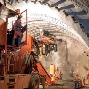
Conventional equipment usually employed in this method of tunnelling was used to excavate the central rock sections. For drilling and explosive placing through the rock sections, Tamrock jumbos with two or three booms were employed. In the more tricky and unstable portal areas, where soil and decomposed rock made up the bulk of the geology, backhoes and handheld drills were used.
Rock excavation blast patterns were based on a central ‘cut’ with 102mm diameter relief holes. For the central gallery, with a 66m² cross section, the charge ratio was 1.55kg/m³ with the explosives placed in 45mm diameter holes. The contour holes had staggered charges and the remaining holes were packed with a full charge.
The excavation cycle consisted of three daily 6-hour shifts, resulting in a production rate of two 0.8m advances each day in the portal soil sections and 3m per day in the tunnel’s central rock sections. These figures apply for each excavation compartment of the tunnel cross section (Figure 2).
Final observations
On completion of the tunnelling works an analysis of the construction experiences allowed some valuable observations to be made:
Related Files
Figure 2
Fig 1 – location map


