The arrival of the ‘C320 – Thames Tunnels’ TBM into its cut and cover reception chamber, employed a new technique involving the use of glass-fibre bars (GFRP) instead of steel reinforcement for construction of the diaphragm headwalls. This technique enabled the TBM disc cutters to cut through the wall with ease before entering a pressurised sealed chamber, located inside the box and mounted on the headwall. This is the first time in the UK that the method has been used, omitting the need for installation of a thick slurry block to guard against inundation into the box during breakout.
The Channel Tunnel Rail Link (CTRL) is the UK’s first high-speed rail project, and the largest new passenger railway in Britain for over 100 years. When completed, at an estimated cost of US$8.18bn, CTRL will link the Channel Tunnel with a new terminus located at St Pancras in London. The works involve the construction of 109km of new high-speed railway with intermediate stations being provided at Stratford in East London and Ebbsfleet in North Kent. Section 1 extending from Fawkham Junction to the Channel Tunnel is nearly complete. Construction on Section 2 extending northwards from Southfleet Junction, Gravesend to St Pancras commenced lin 2001.
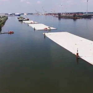
The US$220M, C320 Thames Tunnels forms part of Section 2 and carries the CTRL beneath the River Thames (Figure 1). The contract was awarded to the Hochtief/Murphy JV in January 2001 and comprises twin, 2.5km long, 7.15m internal diameter bored tunnels, and 1.2km long approach structures.
Tunnelling works
Both of the tunnels are being constructed from Swanscombe Marshes, on the south side of the River Thames, and will pass under the river before emerging at West Thurrock, on the north side. The Herrenknecht Mixshield slurry TBM is approximately 35% open-faced, with 140 scraper tools and 17 double disc cutters mounted into the cutterhead to deal with the highly abrasive flints. The hydroshield operates at face pressures of up to 4.5 bar, slightly above the maximum hydrostatic head existing at the nadir, but to date pressures of up to 3.5 bar have been sufficient to adequately control face stability and ingress of excessive water within the chalk drive.
The tunnelling works of Contract 320 are the first in the UK where a slurry/hydroshield TBM penetrated through a “soft eye” headwall into the reception chamber. As a consequence, prior to commencing construction of the “soft eye” headwall a reduced scale trial was performed and the results analysed, confirming the design assumptions.
For the trial and subsequently for the main construction, the “soft eye” was reinforced with GFRP (glass fibre-reinforced polymer). The advantages of the material were the high longitudinal strength (even higher than steel) in combination with the low transverse strength. These properties not only enabled the reinforcing of the diaphragm wall, but also allowed the TBM to drive through the wall perpendicular to the main rebars without any problem.
However, one disadvantage of using GFRP bars is the lack of yielding before brittle rupture and the low modulus of elasticity (~20% of steel). Hence the diaphragm wall thickness at the reception chamber head wall had to be increased from the standard 1.2m to 1.5m.
Manufacturing of GFRP hybrid cages
The headwall of the reception chamber was constructed in standard diaphragm wall technique. Each prefabricated reinforcement cage was ~1.9m wide and ~1.3m thick. The length of the cages reached nearly 30m. There were always three cages in one 6.85m wide trench, since the handling of one single cage was not practical due to the heavy weight and the increased geometry.
Each of the main tensile GFRP bars comprised bundles of four single bars of Ø32mm (4 x Aslan 100 GFRP rebar). The bundles became necessary, since the maximum available diameter of the GFRP bars was 32mm. There were several discussions about the bond that could be applied for the structural calculation and for the required lap length of the bundles. It was decided that, due to the reduced bonding, the ultimate capacity for each single bar was set to be 1.2 times lower and the lap length was increased accordingly.
The shear reinforcement was made out of bundles of two rebars Ø16mm (2 x Aslan 100 GFRP rebar). These bars had to be bent at the factory (“hot bends”), as any bends on site were not possible and would have had required special equipment. Therefore the shear reinforcement bars were designed as U-shaped bars to enable easy installation.
The idea to manufacture the whole cage out of GFRP bars was not economical, since the cost of these bars are much higher than the cost of ordinary steel bars. To reduce this cost, even the outer cages had been designed with only a part section of GFRP bars. In the final cast condition the connection between the GFRP bars and the steel bars was assured by a lap length of 2.0m.
In total, eight GFRP hybrid cages were required, four for each of the two tunnels, with the GFRP area positioned according to the shape of the tunnel opening and with a tolerance of about 350mm to the theoretical breakout of the TBM. The outer diameter of the TBM was 8.15m, but the diameter of the “soft eye” had to be increased to 8.85m to take account of the following additional tolerances:
i) Tolerances of the approach of the TBM. These are associated with survey errors along the complete drive length (2.5km) and the possibility of some vertical movement just in front of the diaphragm wall, caused by varying soil conditions. These tolerances were assessed to be ±150mm.
ii) Tolerances of the placing of the reinforcement cages in the excavated trench, which in the worst case could still be found during the casting of the diaphragm panels. These tolerances were assessed to be ±200mm.
Nevertheless, the hybrid cages had to be installed like a normal panel into a bentonite filled trench. Therefore they had to be lifted in vertically, which resulted in a required load transfer of the lower steel part via the GFRP bars into the upper steel part and then into the crane hook. Together with the subcontractor for the diaphragm walls (AMEC/Spie JV) a clamp connection was developed and tested. The test, performed with a torque of 25Nm to each nut of the clamps, demonstrated a SWL of 3.3kN for each clamp, which was more than sufficient for the maximum required load transfer of 12t via 18 structural applied connections with three clamps either side.
Lifting of GFRP hybrid cages
The standard steel reinforcement cages were completely prefabricated and strengthened by braces, which were welded to the T40/T50 rebars inside the cages. This made it possible to lift the cages with two cranes from the horizontal into the vertical position. Due to the nature of the GFRP-bars, welding in the vicinity of the fibre bars was not possible. Any mechanical strengthening would have ended up in a huge amount of fixings just in the area of the TBM breakthrough and would have ruined the concept of a “soft eye”.
The final applied solution was to assemble the hybrid cages in the horizontal position by solely using binding wire for the fixation of the fibre bars and afterwards to lift them horizontally with two cranes and an arrangement of spreader beams into a tilting frame. Following this operation, the relatively fragile structure could be moved without any introduction of relevant bending forces.
Once the cage was resting and supported in the tilting frame, both the tilting frame and the cage could be lifted by individual cranes. After the frame was lifted up into the almost vertical position, the cage could be lifted out of the frame and moved to the trench.
After lowering the cage into the trench the panel was concreted. A modified concrete mix with a smaller aggregate size was used over the depth where the GFRP reinforcement existed. This was in order to avoid any problems due to poor concrete flow around the rebars, especially due to the high amount of reinforcement in the lap area. The good quality of the diaphragm wall in the area of the “soft eye” was confirmed once the excavation of the reception chamber was completed.
TBM drive through the soft eye
More or less one year after the installation of the diaphragm wall, the TBM arrived on the north side. The final approach of the last 10m up to the diaphragm wall was performed with a speed of advance limited to less than 20mm/min and a maximum thrust force of 1,500kN. The final drive through the diaphragm wall was performed slower, with a speed of advance of approximately about 10mm/min.
The headwall was permanently checked by different monitoring systems. One of these was a string line placed on top over the whole width of the headwall, which allowed everybody directly involved with the operation to check any movements of the wall. In addition, inclinometers in the headwall and strain gauges in the propping were monitored. During the slow advance no significant movements of the headwall were reported and the loads in the props were as predicted. In this way the TBM crunched its way slowly through the C40 concrete and GFRP bars.
Pressure Release Chamber
At the reception chamber the tunnel is located within alluvial clays and peats in the upper half and the Thames gravels in the lower half. The gravels are very permeable and the fluctuation in water levels is related to the tidal influence from the River Thames. For the final TBM drive through the wall it was therefore essential to install a sealing system in front of the headwall.
The complete system consisted of an adjustable sealing ring fixed to the diaphragm wall and covered with a bulkhead. The bulkhead was supported by an abutment, constructed from the bottom and top slab of the open cut. On arrival of the TBM, the chamber was pressurised with water to about 1.3 bar at the level of the tunnel invert.
The design of the Pressure Release Chamber (PRC) was based on the continuously developed know-how gained on several other tunnelling projects and was modified by the designer Hochtief Consult for the prevailing C320 conditions.
Due to the excellent work of the surveyors and the experience of the TBM driver, the breakthrough on 4th March 2003 was completed within a tolerance of less than 20mm; less than the diameter of one penny!
After breakthrough of the TBM, the material that had fallen into the PRC had to be removed under compressed air. This work took approximately 48hrs. Then the sealing ring, which could accommodate a tolerance of ±150mm in each direction, was moved into the correct position. The TBM pushed itself forward a few centimetres into the sealing ring and the sealing ring inflated.
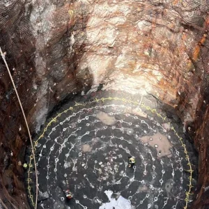
After the decompression of the PRC the small manhole in the bulkhead was opened and the cutterhead exposed. The removal of the abutment construction and the bulkhead was then performed quickly, and the cutterhead of the TBM inspected over its full size (Figure 2).
Related Files
Fig 1 – Map showing C320 on the CTRL section 2 alignment
Fig 2 – The breakthrough sequence, a first for the UK