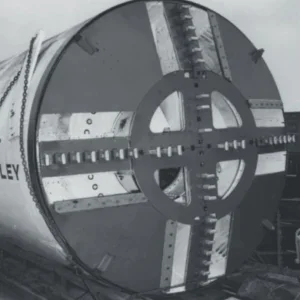
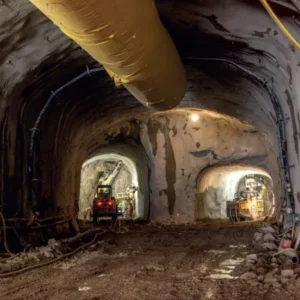
The Porto Metro is a 70km light rail system currently under construction in Portugal’s second largest city. The underground component of the metro consists of two tunnels (Line C, 2.5km; and Line S, 4km), driven by two Herrenknecht EPB shields of 8.7m and 8.9m diameter respectively. The two tunnels will serve 10 underground stations. Civil works were awarded in 1998, to a JV of Soares da Costa, Somague and Impregilo. Geodata was contracted by the JV for geological-geotechnical characterisation, tunnel design, building risk assessment and, with Mott MacDonald, resident engineering services during construction.
Tunnel construction for Line C began in June 2000, but was soon interrupted by three major collapses in October 2000, December 2000 and January 2001. In order to overcome these initial difficulties, which led to nine months of TBM stoppage, a new integrated team approach was adopted in 2001 for both the design and construction phases.
Tunnelling for Line C was successfully completed in October 2002. Excavation of Line S began in June 2002 and was completed at the end of October 2003.
Project overview
The 7.8m and 8m i.d. tunnels are both lined with a 1.4m long, 300mm thick, tapered universal ring, consisting of 6+1 pre-cast, reinforced concrete segments. The tapered rings allow a minimum radius of 200m.
Overburden thickness ranges from 10m-30m, with a minimum value of 3m-4m in two sections of the city’s historical centre where the TBM has been driven underneath sensitive buildings. Metro construction interferes with a densely populated urban environment, with more than 2000 buildings in the influence zone, including many important and historical buildings such as the Town Hall. A specific risk assessment was performed for input into the design of preventive measures. Finally, a GIS-based monitoring system was put in place to control the effects induced by tunnelling and to activate the counter-measures.
The site is underlain by igneous rocks, representing the “Granito do Porto” formation. It consists of a two-micas, coarse granite, greyish in colour, changing to yellowish when weathered. Alluvial material is often found above the weathered granite due to the presence of several water courses, most of which are covered due to the intense urbanisation of the area. The granite is weathered to different grades, from fresh rock to residual soil, showing highly variable conditions.
The weathered granite locally exhibits a metastable structure, which can accentuate the potential for collapse, depending on the high porosity and reduced cohesive strength of the loosed/leached residual soil. Consequently, the ground tends to follow an elastic-brittle-plastic behaviour, leading to sudden, unforeseeable failures at the surface with practically no warning if the tunnel face is not properly supported or if uncontrolled over-excavation is allowed.
The water table is located 10m-25m above the tunnel, and roughly follows the shape of the surface topography. A large number of old wells and “minas” (old and small handmade water tunnels) are present in the area, with no historical information available. The vast number of these wells and “minas” have modified the hydro-geological characteristics of the ground, so that the groundwater moves not only in the porous medium and fractures, but also along the preferential channels represented by the “minas”, which strongly influence the underground water circulation.
The design approach – TBM advance plan
Due to the extreme variability and unpredictability of the geological conditions and surface constraints, the EPBs have only been operated in closed mode.
When excavating with an EPB in urban environment, the main concern is to reduce, as much as possible, the face and volume loss ahead, above and behind the TBM so that settlements are maintained within acceptable limits. The extent of these limits is obviously based on the amount, type and condition of the buildings reached by the subsidence trough.
The design should therefore address the following: definition of the correct TBM working parameters to minimise face and volume loss; estimate of the extent and shape of the settlement trough; evaluation of the acceptable deformation limits of the buildings; definition of both preventive and remedial measures.
To deal with these in detail, the design package PAT (Plano de Avanço da Tuneladora or Plan for Advance of TBM) was related to tunnel sections ranging from 200m to 1km, and included the following documents: report on the geological investigation and its interpretation; report on building risk assessment; report and drawings about the monitoring of underground structures and surface buildings; report on the evaluation of the TBM working parameters; geotechnical profile with indication of the TBM working parameters; summary report on the Plan for Advance of TBM.
Towards the end of each section, the experience gained was summarised in specific back-analysis documents that helped optimise each subsequent section. Thus, a process of continuous enhancement was implemented, with emphasis on the following:
i) in addition to “traditional” design information, such as geological evaluations and structural calculations, a specific set of TBM working parameters was delivered. In particular, the “report on the evaluation of the TBM working parameters” contained the definition of the reference value and the relevant operational range for: face support pressure; apparent density of the muck in the chamber; weight to be extracted at each ring; longitudinal grouting pressure and volume; additional bentonite slurry injection volume and pressure.
ii) the TBM working parameters were summarised from the PAT and delivered to the TBM crew in a simple form, called “Excavation Sheet”.
iii) following the real-time and back-analysis activity, the Excavation Sheets were continuously updated based on the actual encountered conditions, so that the PAT could be regarded as a live document.
The implementation of the PAT and its continuous update has proved to be a very effective tool, as the geological conditions and the design parameters for the TBM are given in advance together with the instrumentation and the monitoring requirements.
EPB standard and special features
After the Line C accidents in 2000, certain modifications were made to the machine configuration, leading to a higher degree of safety and better overall performance:
In addition to the above, a certain number of significant adjustments have been made to settings of the software used to drive the TBM. In particular, the following three automatic alarm systems have been set up: one alarm for exceeding the extracted weight upper limit, which automatically stops the advance; one alarm for exceeding the face support pressure lower limit, which automatically switches on the SFSS; and one alarm for exceeding the lower limit of the apparent density of the muck.
Construction follow-up
After the initial accidents, three key factors were identified as essential for the re-start of tunnelling works and successful completion:
In regard to this third factor, an integrated TBM follow-up team, consisting of specialists from both the contractor and the designer, have integrated their skills with the aim of achieving the highest possible TBM performance; conforming with the highest possible safety and quality standards; and achieving overall cost optimisation. The organisation of the integrated tunnel team is shown in Figure 1. The main scope of the team was the continuous interpretation of the interaction between the TBM and the ground.
Relationships with the client have been effectively managed through Tunnel Daily Review Meetings. During these meetings monitoring and TBM data were reviewed jointly by the contractor, designer and client representatives and any necessary design changes were discussed and agreed in a timely manner. Furthermore, the daily meetings turned out to be interesting brainstorming sessions, during which all the parties addressed the main topics of the project, often giving useful suggestions for improvements.
TBM performance
One of the key-factors for the successful completion of the project has been the utilisation of the continuous analysis of TBM performance (real-time and back-analysis) as an important working tool. The Porto Metro Project represents, perhaps, the first example of its utilisation on a large-scale tunnelling project. The choice of this tool is based on two factors:
i) being clear that the TBM advance is the potential cause of disturbance to the surrounding environment, and the settlements are the ultimate effect of the TBM advance, both the contractor and the designer agreed to integrate the conventional monitoring system – focused “only” on the effects of the tunnelling, i.e. ground and building movements – with a new system, which would analyse the causes of such movements.
ii) based on the different type of ground (soil-like or rock-like) and the overburden, the delay between the passage of the TBM (cause) and the occurrence of the settlements (effect) can vary from a few hours to several days or even weeks. Hence, when analysing the TBM data, it is in many cases possible to know in advance the potential of tunnelling induced settlements before they reach the surface (or are recorded by the monitoring system). As an important consequence, it is possible to apply counter-measures in a timely manner.
Therefore, with the main scope of anticipating the potentially negative impact of tunnelling at the surface (settlements or even collapses), the TBM engineer was fully dedicated to the analysis of the TBM behaviour, with the following specific duties:
Real-time analysis
Back-analysis
One of the main challenges on the project was to manage the advance through mixed face conditions, fulfiling two different goals: excavating very hard and abrasive granite with satisfactory advance rates; and supporting very weak and loose material resulting from the weathering of the granite.
The above scopes being almost opposite to one another, the analysis of the TBM operation needed to include a wide range of parameters, some of which related to the control of face and void stability, and others to the excavation process itself.
In the first stage, the core of the analysis was the verification that fundamental TBM parameters complied with the specifications defined in the PAT. For each TBM parameter, the PAT defined an operational range and counter-measures to be applied if the attention/ alarm limits were exceeded. At the second stage, as a natural evolution, other operational parameters were included in the study, including:
For these parameters no limits were imposed in the design, but their trends were carefully analysed, as they could give useful information about the ground conditions and correct operation of the machine itself.
Control of the extracted muck weight
The TBM incorporates a conveyor belt system for the removal of excavated material; hence the measurement of the extracted muck weight was carried out by using two belt scales. Thanks to the ability to cross-check the figures recorded on the scales, the system has proved to be generally reliable, with an accuracy of 3-4%. In order to adjust the reference value and the operational range as much as possible, to fit the actual geological conditions, it was necessary to execute frequent face mapping and estimate the ground in-situ density, at least every 15m. The figures recorded on the scales had to be considered as gross weights and before comparing them with the reference value it was necessary to subtract the weight of the conditioning agents added during the excavation (average 20-30m³ of water with polymer). Some fluctuations around the reference value are unavoidable, as the extracted muck weights vary according to the compaction grade of the material inside the excavation chamber, which in turn is highly variable at each ring.
The tunnel alignment included some very tight curves (R=200m); in these curves, due to the misalignment of the back-up gantries and the bending of the conveyor belt itself, the balances were not correctly loaded and the recorded weight figures less accurate.
Management of face support pressure
Together with the weight control, the management of face support pressure is of paramount importance for guaranteeing the successful operation of an EPB machine. The design approach requires the application of a minimum effective pressure. In simple terms, it is required that the support pressure be transferred from the bulkhead to the face via solid particles and not only through the pore pressure or compressed air.
The operational consequence is that the chamber must always be full of solid matter with an adequate density, defined at approximately 14kN/m³. By guaranteeing that the density of the material in the chamber is above this value, two important results are achieved:
As a safety measure, the reference support pressure was defined and measured at the top of the bulkhead (1m below the tunnel crown) so that the other pressures were higher. The density of the muck was evaluated by measuring pressures at different bulkhead heights and dividing the difference in pressure by the corresponding difference in height. Due to the heterogeneity of the material in the chamber, and the dynamic effect caused by both the rotation of the cutterhead and the compression of the bulkhead, the instantaneous density figures fluctuated significantly. Therefore, the density had to be considered “apparent” and not really representative of the actual density of the ground.
Figures 2 and 3 show some example graphs of the instantaneous support pressure data, as recorded on the seven sensors on the bulkhead wall. As can be easily seen, these graphs have proved to be a very effective tool to check the proper EPB closed mode operation.
The correct mix of soil conditioning agents is crucial for achieving good results. In the granite of Porto, both polymer and foam have proved to work successfully. The polymers have been most reliable, even in delicate conditions, but they cannot help to reduce the very high tool-wear rate, which was one of the main problems. The use of foam has instead helped to greatly reduce the wear rate, however, required more complex settings and smoother operation of the screw conveyor.
Control of primary and secondary grouting
Backfilling around the segmental lining was carried out using a longitudinal grouting system composed of six injection lines, evenly distributed around the tailskin.
To check the efficiency of the primary grouting, as a standard practice, grout cores were extracted every ten rings and, if necessary, secondary radial injections were carried out at pressures of up to 4 bar.
In very critical areas, i.e. under sensitive buildings with low cover, the conical void around the machine was filled with bentonite slurry, continuously injected through ports located along the shield. This provided additional help to further reduce volume loss due to the TBMs’ passage.
Face conditions and TBM parameters
Analysis of the TBM operational parameters allows detection of the ground conditions, as traditionally seen in oil drilling or geotechnical investigation campaigns. In particular, the combination of cutterhead thrust, advance speed and disc wear gives a clear idea of the face conditions, e.g. the harder the face, the higher the cutterhead thrust and disc consumption; the harder the face, the lower the advance speed. Thanks to frequent face surveys, it was possible to accurately calibrate the interpretation of the trend of these parameters and then, whenever a direct survey of the face was not carried out, it was still possible to recognise the ground conditions through which the TBM was advancing. Figure 5 is interpreted in a matrix format (Figure 5 Matrix Table):
The use of such a matrix and of the above mentioned graphs has proved to be a key factor in foreseeing the trend of the settlements at the surface.
TBM production and utilisation rates
Despite the very delicate situation in which the project has been developed, it has been possible to achieve very good results in terms of advance rate and production. The TBMs were normally operated on a 24hr basis, working a six-day week. Almost one shift per day was used to execute cutterhead maintenance under hyperbaric conditions. The following main results have been achieved:
The site management and level of skill of the workers is shown in the very high TBM utilisation rates. Considering that the two TBMs have been operated in a very sensitive urban environment – always in closed mode – these results can be regarded as very positive and above the usual standard.
Related Files
Fig 1 – Tunnel team organisation chart, where the contractor and designer representatives are inserted in elliptic and rectangular frames, respectively
Figure 5 in matrix format


