TBMs were the obvious choice for the twin drives of the 4.6km-long Legacy tunnel in the Queensland capital of Brisbane. Not only are hard rock machines well suited to the sound igneous rock underneath the houses of the well-off western suburbs, but also because there were machines available in the city.
"We are using the Herrenknecht machines which drove the tunnels underneath the river for the Clem 7 link," says Matteo Ortu, tunnelling construction manager for the three-company Transcity construction group that began work on the AUD 1.5bn (USD 1.44bn) project in 2010.
"They have been been reconditioned by Herrenknecht." The manufacturer has an Australian depot near Brisbane Port where the work was being done.
Make do and mend
Acquiring and using the machines makes obvious sense in that the geology is similar, though not identical to the first tunnel. The TBMs also happen to be the right size and capacity. Like the Clem 7, which opened in 2009, the Legacy tunnel will be a twin, two-lane motorway, running beneath and into the central part of the city, which has been growing more and more congested.
The first, Clem 7, tunnel runs from the southern suburbs underneath the Brisbane river, and the new tunnel will bring in traffic from the west. It is part of a roughly triangular ‘ring’ of underground links for the city which sits on the Brisbane river estuary some 20km from the Pacific coast. One of the fastest growing in Australia, it has been becoming increasingly congested.
The Transapex project, as it is called, has so far seen the building of the Clem 7 and the Y-shaped Airport Link into the northern suburbs and as the name suggests to the airport near the coast. Legacy will serve the western and inland side of the city, relieving traffic loads coming in from the Western Freeway, which currently passes through the university area and a well-off western residential sector. It will carry flows underground to link with the important Inner City Bypass. A fourth tunnel is planned that will complete the triangle in the south.
Funding
The new tunnel is being funded somewhat differently to the first two tunnels, which have seen major financial difficulties since they began. Both these were full private public partnership schemes with long period toll concessions that have been undermined by the onset of the world credit crisis and lower toll revenues than expected.
For the Legacy tunnel, formerly known as the Northern Link, the Brisbane City Council has let the project on, essentially, a design and construct basis to Spanish tunnel and civil infrastructure company Acciona. The company takes the lead in a joint venture with Italian tunnel construction specialist Ghella and Brisbanebased BMD Constructions. A 10-year concession, for maintenance only, is part of the contract paid on an availability basis, but tolls will be collected and disbursed directly by the client, using a separate operating company.
Design work for the tunnel has been subcontracted to a ‘design alliance’ of US consultant URS, GHD and Cardno. For construction the western end of the project, rather than the busier inner city end, sees most of the action. A major operations site here houses all backup and stores for the project and the starter pits and portals for the TBMs. Work started here in April 2011.
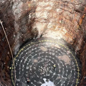
The first job ironically for the TBM drives was some drill and blast. This firstly formed the initial starter pit into the rising ground on the tunnel alignment, along with a secant piled wall to hold back weathered ground at the back. But, but importantly drill and blast was used to create a 560m-long tunnel from the excavation area to a spoil disposal site in the Mount Coot-tha hills just under 1km away. Fortuitously a still working quarry for high grade rock is located there with deep and now vacant areas big enough for the large quantity of spoil from the two drives, around 1Mm3 altogether. The quarry, conveniently, is owned by the city council.
Treading carefully
"The plan was always to use a conveyor system for the spoil," says Ortu. This would save some 96,000 truck movements during the project he says, reducing noise and road traffic, an important consideration even at the western end of the project. The site is situated in a district of pleasant tree-lined avenues and housing, many of the buildings original ‘Queenslander’ style houses dating back a century or so, and in some cases heritage listed. Minimising disruption has been critical.
But the overland conveyor mooted at the beginning would have extended more than twice the length without a short tunnel from the site. Now by passing through a 20m2 cross-section bore, the spoil disposal needs just 870m of conveyor running 15m to 35m deep. The tunnel also contains the spoil underground reducing dust impact.
It ends at a 180-degree distributor conveyor in the quarry. The tunnel took four months to excavate, using an Atlas Copco drill rig.
Noise and disruption is further reduced at the site by enclosing the working areas of the portal and immediate tunnel servicing within a soundproof building. "It is straightforward enough," says Ortu, "just a steel frame with acoustic panelling."
Behind the portal building are site offices, and backup supply facilities including tanks, pipelines and mixing points for grout to the machines, water and water treatment plant and ventilation. "We also have an onsite paramedic facility," says Ortu, "and our own workshop and spare parts store, with a relatively large stock so that we can be fairly independent."
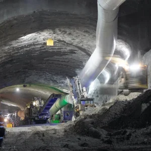
The TBMs, christened Joyce and Annabel began their drives from the 10m-deep, covered starter pit at the end of the site. They are Herrenknecht double-shield machines refurbished and modified.
"They now have a shorter backup train than before with a segment unloading facility and erector, and a conveyor spoil system," says Ortu.
Each makes a 4.3km-long section with the remaining 300m of tunnel in cut and cover works at either end.
The Italian company has its own methodology for drives says Ortu, which focuses the logistics of the TBM process very strongly around segment erection only with the other activities of the tunnelling kept very much as follow up in the tunnel behind. "We have studies that carefully to optimise the sequences and increase efficiency," he says.
Conveyors are supplied by Herrenknecht subsidiary H+R and run down each of the bores and then connect into one conveyor within the start area. From here they continue outside and into the tunnel to the quarry. Capacity of the spoil system is some 2,800t/hour.
The machines themselves have rock cutter heads, with grippers at the side and jacks at the rear. "We use 19in cutter discs," says Ortu.
For most of the drive these are used to get through Bunga Phyllite, which he describes as an intermediate grade metamorphic rock, with high foliation.
"It has a fairly high quartz content which makes it quite abrasive," he says and wear on the cutters is substantial, with an average of five to seven needing to be changed daily. "There is a four hour maintenance break each day when we do that."
Unfortunately the mineral content of the rock makes it mostly unsuitable for concrete he says. "It also produces quite a high proportion of fines rather then a sharply delineated chip structure."
The spoil is useful for road base in the tunnels and site use.
For the launch of the machines an interesting reaction system was used tied into the rock rather than a traditional reaction frame. The and artificial segment rings but pushed off from partial rings formed from just invert segments in the base of the launch cradle just outside the portal.
Once fully in the ground the machine formed its first full segment ring against a special steel reaction ring attached to the portal block with ground anchors through the secant pile wall. The steel ring provided reaction for the first few rings then until the machine was sufficiently far into the ground for the tunnel to provide its own reaction.
The tunnel lining is a universal ring says Ortu. "The ring has eight segments 350mm thick and 2m-long plus a half size key." A possible 17 positions are usable for the ring orientation to form curves and adjust the direction if necessary. A standard VMT laser and target guidance system gives information for that.
"Segments are designed for minimum ring build time," he says. "They are all of parallelogram or trapezoidal shape."
An additional precast invert unit goes in afterwards to form a flat floor to the tunnel during construction. This is important for the delivery vehicles, which are the rubber tyred units increasingly favoured as a means of avoided rail installation in tunnel construction. In this case the units are specially made by French firm Techni-Métal Systemes which was acquired by Herrenknecht in January this year. Rival manufacturer Metalliance has supplied the man riders, however, which carry the crews to the machine each shift.
The segments themselves are made at a precast works ‘down the highway’ using CBE forms and carousel. "The reinforcement is a steel fibre supplied by Maccaferri," says Ortu.
A relatively small holding area is used to store the rings at the back end of the acoustic shed from where they are lifted into the starter pit below with two portal cranes, a 60t unit and a larger 260t unit. The two cranes had been used for the TBM assembly initially and the larger unit was required mainly for the head shield.
That operation took 80 days for the first machine and 73 for the second says Ortu, "which we did ourselves though with technical input from Herrenknecht."
Now the cranes lift the segments down in groups of three onto the delivery vehicle which rakes them to the back of the machine where a fast unloader unit moves them forwards to the segment erector at the machine.
The segments are flat faced within the ring but have a grooved connection in the centre of the longitudinal joint. Two plastic cylindrical rods are pre-fitted within the grooves, one each side of the segment to provide shear connection strength.
The rings are then linked ring to ring with a specially shaped connection rod from Fip in Italy, explains Ortu. The dowel slot into holes in facing joint of the segment and remain protruding until the next segment is slid over.
"This system of dowels and jointing rods allows us a very quick erection time for the rings," says Ortu, "and has helped achieve good accuracy on the ring fits with minimal ovalisation." A possible problem with the fast double erection sequence of a telescopic machine is ‘stepping’ between rings or lips where one segment is not precisely seated against the next. Ortu says this has been kept to a minimum.
Once erected the rings are grouted in a two-stage process. First is grouting from tailshield, for the bottom 120 degrees of the ring, to avoid grout moving too far forwards to the machine head.
"Rather than pea gravel, a fast grout is used mixed from cement and PFA with various accelerators and retarders" he says. These include sodium silicate and other additives, supplied by Mapei.
As the machine moves forwards there is further grouting done through the segments from pumps on the back of the TBM train. "We did some full scale trials on the grouting to ensure that the voids were being filled but we were not grouting up the machine head," he says.
Grout is supplied to the machines through a pipeline system from the backup yard above, rather than using delivery in tanks on the tunnel vehicles.
It comes as two components mixed at the end and further retarder in the mix ensures that the lines do not get clogged while they are waiting for the pumping sequences.
The system set up, both in the machine itself and the logistic supply, has allowed good progress, says Ortu, with the second of the machines achieving some excellent drive rates on its 4,260m bore.
Completed in April this saw an average of 30m a day achieved but at one point a maximum 49.7m in one day. According to Transcity project director Fernando Fajardo a "maximum of 248.82m was achieved in one week and a 30 day maximum of 787.78m."
The first of the two machines will not make quite the same progress because it has had to stop along the way to allow for the construction of three cross passages between the two bores, which are about 10m apart. These are not the final cross passages, but rather an initial set required for construction safety purposes.
"For the final tunnel there are cross passages every 120m," says Ortu. Most of these are for tunnel safety and evacuation purposes. Each is 4m wide and 3.5m high and will be fitted with safety doors allowing tunnel users to escape to the opposite bore in the event of accidents and in particular a potentially deadly tunnel fire.
Additional tunnels are needed however bringing the total of the connections to 35. The remaining tunnels in between the escape tunnels are primarily for substations, and in one case for hydraulic sump purposes at a low point in the tunnel alignment.
All the cross passages are being excavated primarily with hydraulic rock hammers, and possibly some controlled drill and blast, says Ortu. For safety purposes, remote-operated Brokk excavator units are being used for the work, a Brokk 400 and a Brokk 800.
"The advantage of using Brokks is their capacity to operate in confined spaces, while still achieving the same performance as larger excavators, and their remote control safety features," says Ortu.
The smaller unit will use a half tonne hammer and the larger a 1.2t variable frequency hydraulic rock breaker, he says.
With the excavations complete there is extensive fitting out to be done for the tunnels. A key feature of this is installation of a smoke deck within the tunnel allowing for a highly controllable venting system for fumes and smoke in the event of fire. Vent flaps will be able to operate every 60m to isolate areas of fire and exhaust hot gases and smoke.
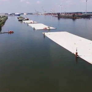
The TBMs meanwhile have to be disassembled. This will take place underground in the last short 100m section of the tunnel alignment, which has been built in a cut and cover at the western end of the project, an area called Kelvin Grove where the new road will connect into the city bypass. Keeping the excavation top down has helped with the complex traffic management required for the works at either end, to keep existing ‘flows’ of traffic moving, at least as well as they have in the past.
"The reception chambers have been built by a top down method with secant pile walls," says Ortu. They form part of the tunnel and are already roofed so that machines cannot be dismantled with standard cranes.
"We are using a system of strand jacks to lift the various components of the machines," he explains.
After that there remains M &E for the tunnels, lighting, monitoring video and fire detectors, variable message signs and lane control signalling and the automated tolling gantries. Like all tunnels in Australia these have to allow interchangeable tolling with other parts of the country.
The tunnel is due to open next year and looks well set to do so at present