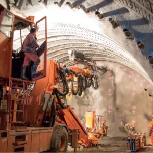
Which methods do you use most frequently for boring tunnels and why? All of the hydroelectric projects of Neepco are located in the Arunachal Himalayas, Shillong Massif, Naga Patkai Range and Mishmi Hills region of north eastern India. This region is tectonically active in nature and comprises large numbers of active shear and fault zones. Here, geotechnical parameters such as RMR, Q value etc. of rock type encountered during tunnel boring varies considerably for one tunnel length. Therefore, conventional drilling & blasting and NATM methods have been used.
In the Arunachal Himalayan region, the rocks of Siwalik Formation, were folded and uplifted to give rise to Sub Himalayan ranges and demarcated by the HFT (Himalayan Frontal Thrust) from the alluvial of Brahmaputra. Gondwana sediments of lesser Himalaya are separated by the Main Boundary Thrust (MBT) from the Neogene sequence of Sub Himalaya. MCT (Main Central Thrust) separate the lesser Himalaya from the central crystalline zone of Higher Himalaya.
The compressional tectonic stress regime in the Himalayas has resulted in intense deformation of the rock mass, making it highly folded, faulted, sheared, fractured and deeply weathered. This complex geological setting has caused considerable stability problems and is a great challenge for successful tunnelling. The complexity is represented mainly by four engineering geological characteristics, which have caused major stability problems during tunnelling.
These are:
- Weak rock mass quality,
- High degree of weathering and fracturing,
- Rock stresses,
- roundwater effect.
The location makes ground investigation studies difficult. How do you research the conditions before tunnelling?
The Arunachal Himalaya, Shillong Massif, Naga Patkai Range and Mishmi Hills region of north eastern India is a mountainous terrain (sometimes the overburden is over 1,000m) and full of vegetation which made the geotechnical investigation prior to tunneling very difficult. Due to tough terrain and heavy vegetation, the detail surface mapping throughout the tunnel length is nearly impossible. Therefore, the geotechnical data such as lithology, faults, folds, joint sets, dip and strike direction of the geological features, RMR, etc. are gathered through the surface geological mapping from the exposed areas throughout the tunnel length and by drill hole data. This geotechnical information is further used to extrapolate the probable geology throughout the tunnel length to prepare the probable L Section, X section of the tunnel and geological plan.
What is your experience of TBMs – do you use them and will you use them in the future?
All of the hydroelectric projects presently executed and to be executed by Neepco are in the Arunachal Himalayan, Shillong Massif, Naga Patkai Range and Mishmi Hills region of north eastern India. The terrain here is mountainous and full of vegetation.
Most of the areas in this region are widely inaccessible for detail pre-construction geotechnical investigation along the tunnel alignment. In some cases the overburden is more than 1,000m and therefore pretreatment of the tunnel is practically not possible. Heavy ingress of water through weak or shear zones make the tunnel boring more difficult. The existing roads in these hilly regions are very narrow and with lot of sharp bends. Therefore, at this stage economic viability for using of TBM is a matter of concern. However, in course of time improvement in road communication using of state of art technology for geological investigation in such a difficult terrain and TBM equipped with a provisions for effective advance pre injection grouting, wet shotcreting, advance forepoling, bolting and probe drilling etc., tunnel boring by TBM can be used in future projects.
Case study: Kameng Hydroelectric project, Arunach al Pradesh
Various geotechnical problems, from cavity formation and blow out, to water ingress and faulted distressed rock, challenged Neepco during construction of the 14.5km head race tunnel for the 600MW Kameng Hydroelectric project. The 6.7m dia modified horseshoe shape tunnel was designed to carry 140 cumecs, and the construction called for four adits of varying lengths to accelerate progress.
The first major issue was an 8m long, 5m wide, 4m high cavity, angled at 45 degrees upwards away from the centre line, which opened 422.6m into the tunnel at face number 2. This section was a shear zone within banded quartzite. To arrest the cavity muck was dumped at the heading and steel canopy provided. Concrete backfilling was then undertaken with erection of two half arches on the left side. Further backfilling was undertaken behind the new arches before much below the canopy was removed, extending the half arch. However after much removal a small opening formed at the far right of the cavity through which heavy pressure mud flowed into the tunnel damaging the new supports. The loose muk was a mixture of angular to medium coarse quartz and kaolin clay. Water seepage was also observed.
By drilling 21 probe holes the team determined the extent of the loose muck at around 4-5m from the loose zone, which was over 7m from the face. Restoration required a host of measures and took around 7 months to complete. Initially grouted forepoling pipe rings were placed followed by box girder steel supports. The tunnel alignment itself was slightly lowered and steel lagging was used in the new support system for placing the concrete. As kaolin clay was present in the critical zone chemical grouting was required for stabilisation and prevention of water ingress rather than ordinary cement. Perforated forepoles of 100mm diameter, 12m in length were placed at 500m centres with microfine cement grouting undertaken through these. A secondary ring was placed between the first providing further stabilisation.
Blow outs too were an issue on the project with significant incidents at chainages 616m and 1,337m. In both cases the blow outs were combined with major water ingress flooding the tunnel. At chainage 616m the tunnel encountered a major fault zone along the axial plane of a major syncline fold. A large accumulation of groundwater in the core of the syncline fold was put under additional pressure due to the gradual rise of the tunnel cover, triggering a blow out. Consolidation grouting was undertaken as a preliminary measure, and drainage holes placed in the heading to channel away the water. Remediation included pipe forepoles with cement grouting and took 9 months to complete. The second blowout was completed in 5 months.
A number of key lessons were learned from this scheme including the need to allocate sufficient time and resource to determining the geotechnically critical areas during design stage and ensuring that remediation measures are included in the contract documents. The inhospitable terrain, poor infrastructure and limited time and budget meant that this was not done for the Kameng project which posed contractual problems during execution of remedial works


