The northern line extension (NLE) is an integral part of development to the Vauxhall, Nine Elms and Battersea areas of London. The project calls for new stations at Nine Elms, which will be the penultimate destination, and Battersea Power Station where the service will terminate. Two bored tunnels approximately 3.2km long will run from Battersea Power Station to the Kennington loop, connecting to the existing Charing Cross branch of the Northern Line via two newly constructed step plate junctions.
This solution will avoid a long-term closure of the Kennington loop, which would severely affect service on the existing Northern Line. Cross passages at three locations along the tunnel alignment will form connections between the northbound and southbound tunnels to provide evacuation routes. Modifications to the existing Kennington Station will also be made, including four new cross passages to manage increased passenger flow.
The project is due to be completed by 2020 by main contractor Ferrovial Agroman Laing O’Rourke (FLO). New northbound and southbound tunnels will be primarily excavated using two 6m-diameter EPBMs, launched in February. The 100m-long TBMs with an installed power of almost 2MW are capable of tunnelling up to 30m a day and have teams of around 50 people operating them. Six diesel locomotives manufactured for the project by Schoma in Germany, are equipped with the latest low emission engines and will supply materials to the TBM as well as manriding facilities for the workforce.
One full ring will consist of five full segments with arc length of 3,063mm and one key with arc length of 1,021mm. The alignment of the tunnel is achieved using specific configurations of rings. For example three consecutive left rings will provide a left curvature (and similar for right curve), however an alternating left and right ring configuration will provide a straight-ahead alignment. Segments will be bolted together using Grade 8.8 M24 bolts. The rings are designed for the project by Mott MacDonald and fabricated by Morgan Sindall in Kent.
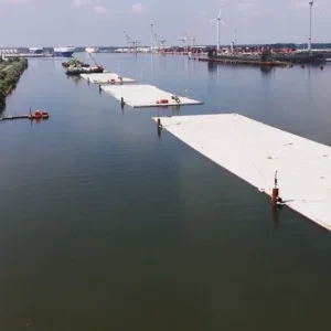
Senior project manager, Mark Thompson says: “To assist the TBM we have a number of supporting systems. Material excavated at the face is removed via a screw conveyor onto a TBM belt, with two calibrated weighers; then onto the tunnel conveyor back towards the crossover box. It is then transferred to a High Angle Conveyor, taken to the surface and deposited into the site muck bin. To facilitate rapid conveyor extension two conveyor loop towers are installed, which can feed additional lengths of belt as the tunnel progresses. The conveyors are all supplied by Joy and manufactured in Sunderland.” The spoil from the NLE is being transported to Goshems Farm in Essex by barges along the river Thames. The loading capacity at Battersea Power Station will take many thousands of lorry journeys off London’s roads.
LAUNCH TUNNELS
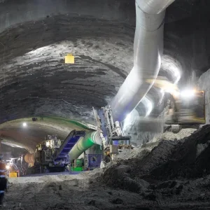
In the Battersea crossover box two sprayed concrete lining (SCL) tunnels were constructed in order to house the TBMs and aid the launch process. These were 75m long and accommodated a shove frame at the face from which the TBM could launch. The tunnels were constructed from a top heading and invert and then later a full-face excavation. Advances of 1m at a time were achieved, excavating with a Schaeff tunnel excavator.
Works were controlled by a daily review meeting containing a representative from the client, contractor and designer. The shotcrete mix was designed for the NLE and supplied by Cemex from their Doveholes plant, with admixes and support from Normet in Coventry.
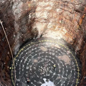
Once the TBM has completed its drive, it must be removed from the tunnel. In order to do this two 26m-deep secant piled shafts with a SCL formation in the pit bottom were constructed at Kennington Park and Kennington Green. Extensive dewatering was put in place at Kennington Park as the base of the shaft ran into the Lambeth measures beneath the London Clay with the potential of running water. Installed by WJ Dewatering, the 13 wells have successfully controlled water ingress along the shaft and the spray concrete lining tunnel alignment.
At the pit bottom a back shunt was constructed to allow the breakthrough of each TBM. In the opposite direction there is a spray concrete lining running tunnel (80m – Northbound; 280m – Southbound) constructed to connect the shaft to the existing Kennington Loop. Like the launch tunnels, 1m advances were completed by a tunnel excavator. A full-face excavation was adopted to remove the construction joint and to reduce noise and vibration beneath the residential area. The surveying system utilised the Amberg system for alignment and excavation controls.
“With the shafts being located in a residential area, combined with 24/7 working in the tunnels, acoustic buildings were constructed over both shafts in order to minimise disturbances to surrounding properties,” Thompson says. Silent ventilation fans were installed within the buildings and a 50t overhead traversing crane supplied by Kone was used for supplying materials and hoisting spoil. The SCL silos, pumps and the muck bin were all contained within the acoustic building, which was supplied and built by Dam structures in Yorkshire.
STEP PLATE JUNCTIONS
Thompson explains that the connection between the new bored tunnels and the existing Northern Line (Kennington loop) is being achieved by constructing junctions on each of the North and Southbound tunnels.
“The construction process included the excavation of a spray concrete lining pilot tunnel directly next to the existing tunnel, using SCL techniques,” Thompson says. “From this opening, the existing cast iron tunnel was exposed on one side. An over dig then exposed the top of the cast iron tunnel, with megashore props and pre-tensioned steel cables being installed to minimise any defection and movement of the Northern line, which has remained in service throughout the works. Timber headings were then created underneath the existing cast iron tunnel. Once completed they were filled with concrete, utilising glass fibre reinforced cages to assist manual handling.
“This further secures the base of the existing tunnel and minimises settlement. The tight side of the existing cast iron tunnel was then excavated in stages using timber headings up to the overdig, all accessed from beneath, completing the excavation all around the existing tunnel.”
The main structure of the new Step Plate Junction is then created using two sizes of Spheroidal Graphite Iron (SGI) segments, respectively 9.5m and 6.5m diameters. Supplied by DTS, these SGI segments will envelop the existing tunnel and will form the transition between two separate tunnels into one. The tunnel lining will be formed by precast concrete rings with internal and external diameters of 5.2m and 5.7m respectively.
“Handling these segments is quite a challenge to get them in place, so we have specifically commissioned Tunnelling Engineering services to provide a segment erector to help manoeuvre segments into position on the TBM,” says Oliver Newman, engineering manager at FLO. Newman says: “Whereas earlier step plate junctions had been formed entirely using traditional squareworks tunnelling techniques, we sought to maximise the use of sprayed concrete lining. This included excavating around the existing railway tunnel in a crescent shape. We have taken the SCL as far as possible, leaving squareworks in just the invert and ‘tight side’ of the existing tunnel.”
“This major advance in mechanisation of the works is probably the aspect of the work we are most proud of.” Thompson explains that work on the Step plate junction is still on-going and they expect to complete it by July, and then will do cable diversions. After that, they will secure the necessary permissions in the autumn to connect the new and existing Northern line tunnels together. “We will do it in a series of 52 hours,” Thompson says. “We have to do a short-term closure of the Kennington loop at Christmas to take out the old cast iron inverts and track bed and then create a new invert and install the new track turnout and connecting rails, thus connecting the NLE to the existing Northern line. “The plan is to minimise any impact on passengers because, over Christmas, London Underground can divert trains from the Bank branch to the Charing Cross branch,” Newman adds.
TUNNEL CROSS PASSAGES
Over the 3.2km of tunnels there are three cross passages to provide emergency exit routes. “We have three cross-passages between the TBM tunnels, two are entirely in London Clay and another one is placed 50 per cent in the clay and 50 per cent in the Lambeth Group, which is dewatered,” Newman says. “However, we were very lucky with the geology because we will be tunnelling almost entirely in London Clay. ”These three cross passages will be excavated using a tracked excavator and constructed using a 200mm spray concrete primary lining. The connection between the tunnel cross passages and the TBM tunnels will be achieved by using spheroidal graphite iron (SGI) segments with four 1,200 x 1,600mm opening sets. Each SGI ring will contain 11 segments including 1 key and 2 removable opening panels. The segments are connected to each other using M24 bolts with hydrophilic grommets and gaskets. Once the cross passage is ready to be excavated the two opening sets will be removed revealing the open face.
“To relieve the increased customer flows resulting from the introduction of the NLE, four new cross passages will be constructed in Kennington Station,” Thompson says. “They will be situated on the Kennington Station platforms and will connect the Bank and Charing Cross services on both the Northbound and Southbound platforms.”
Each cross passage will be formed by SGI rings with an internal diameter of 4,400mm and will be excavated through timber headings. Each ring consists of 10 ordinary segments, two top segments and one key segment.
MONITORING
Extensive monitoring has been installed along the route, both in terms of monitoring ground movement in the extensive Georgian and Victoria properties around Kennington, but also along existing key assets including the current Northern Line tunnel, where shape arrays and frequent track and manual surveys have been used to monitor movement. The proactive review of monitoring led to a slight change in excavation sequence at Kennington Park to reduce loading on the existing cast iron tunnel and the lessons were then applied to the longer excavation at Kennington Green.
“As a project we have a wealth of ground movement and monitoring experience,” Newman explains. “We have the automated monitoring to control in real time, displayed in our Settlement Valuation and Analysis Tool (sVAT) database, and that’s a key aspect of the work. We can watch the rate movement and we can change methods as a result of that. We were fairly flexible in our design so we found the best solution to keep the job going.
“In terms of digital engineering we have a strong culture of using 3D models not just for the design but also to plan the works. For example, every time that we brief a method we use 3D images, which show the works in progress and bring the next stages of work to life. In this way we can think ahead and plan the next stage of the work.”
ATMOSPHERE
“An example of the use of the 3D model was to give us much greater clarity on the conditions the team would face in the tunnels,” Newman says. “Being able to identify where there would be dead-ends where the environment would likely be hot, humid and generally challenging meant we changed our temporary works sequence to greatly improve access and ventilation.”
CONSTRUCTABILITY
Newman explains the reference design included five steps and rings. So the original lengths were 100m for the longer tunnel and 91m for the shorter tunnel. “But we ended up with a reduction to 60m for the longer and 53m for the shorter one,” Newman says. “We knew minimising the workload was key to achieving our tight delivery programme so we worked the designers hard. Having overall control of the design made this possible, especially the track.
London Underground had generated 3D cloud surveys on the track and tunnels which FLO supplemented. We spent a long time looking at the exact positioning of our tie-ins to the existing track – only with the high resolution information did we have confidence to shorten our tunnels rather than assume a longer length to allow for uncertainty.”
“The largest diameter of the junction had to accommodate the 3.8m diameter of the existing tunnel and the new tunnel which is generally 5.2m. We wanted to minimise this end of the tunnel to reduce ground movement so we focussed on efficient solutions for the emergency walkway and tunnel services. Fire, ventilation, architects and pretty much all of our disciplines were a big part of our tunnel design. Reducing the diameter by 1.1m allowed the overall cross section of the tunnel to be reduced by 20 per cent.”
Thompson adds: “We also reduced five headwalls to three and removed gallery headings and compensation grouting. So we simplified the project in terms of level effort.”
Regarding the impact on the surrounding areas of the NLE project, Newman explains they have a community liaison team to make sure residents are informed about what is going on. “We try to adapt to their needs and pursue changes that minimise impact,” Newman says.
According to the government the NLE project will create up to 25,000 new jobs and 20,000 new homes, and it is essential to improve transport links to the area


