The Riachuelo is one of the most polluted rivers in the world. It takes sewerage and industrial effluent from Buenos Aires and empties it into the River Plate. Calling the Plate a river is perhaps misleading: though it is formed by the confluence of the Uruguay and the Paraná rivers upstream of Buenos Aires, many geographers regard it as being entirely an estuary, one of the largest in the world. If it is a river it is also the widest in the world, some 200km across where it meets the Atlantic, with Argentina on one shore and Uruguay on the other. Whether estuary or river, the Riachuelo flows into it, draining the City and Province of Buenos Aires, areas which have seen huge population growth and industrialisation. The Riachuelo carries untreated industrial discharge and the sewage of around four million inhabitants – a fetid mix of heavy metals, chemicals and organic effluent is one graphic description – making it a rival in pollution terms of the Ganges in India and the Pripyat near Chernobyl.
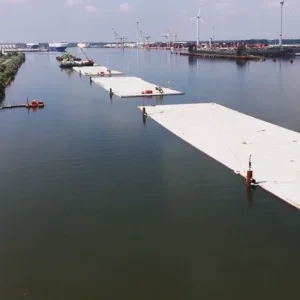
In 2008, Argentina’s supreme court ordered a sanitation scheme to be built to cleanse the river. Intended to have a capacity of 24m3/s, design changes along the way mean that it will be able to transport effluent at a rate of 27m3/s. Now nearing completion, the scheme will provide a long-term sustainable solution for the safe disposal of wastewater from Buenos Aires. It involves not only around 12km of outfall tunnel under the River Plate, which makes it the longest subfluvial tunnel ever constructed, but also, at its end, a system of 34 vertical riser pipes, discharging into the estuary far from shore and thence into the Atlantic. Remarkably, these pipes have been installed from within the tunnel itself. They have been pushed upwards through the segmental lining and though 30m of riverbed to emerge in mid-ocean in an operation performed almost entirely from underground. It is a completely new, imaginative and complex technology, devised and carried out by Italian engineers at Webuild, and has potential in many other projects.
HANDLING THE PRESSURE
The tunnel is remarkable. The effluent it will carry is fed by gravity, and will exert an internal pressure of around 5.5bar. The external pressure, from the river and riverbed above, is around 4.3bar, depending on groundwater and river levels, giving a net internal pressure of more than one bar.
Excess internal pressure is not unusual in outflow pipes: standard designs feature double linings to handle it. The primary outer segmented lining takes compressive forces from outside the tunnel, while a ‘decoupled’ continuously reinforced secondary lining within it resists tensile forces. This was the original plan for the Riachuelo scheme (Figure 1). The tunnel thus constructed was to discharge at around 10km offshore into a single, large vertical transition shaft. From the top of this a 1.5km-long horizontal diffuser pipe at river-bed level and supported on deep piles, would have a series of vertical risers, each around 5m long, through which the effluent would discharge into the estuary.
“However, a comprehensive risk analysis showed that this would present several construction risks,” says Mirko Martini, technical manager for Webuild. The long length of the tunnel would add huge complexity to installing the double lining. “And building the transition shaft would involve intensive offshore dredging activities; these would compromise environmentally the nearby water intakes of Buenos Aires.” Instead, a different solution was adopted. In place of the double-lined outfall tunnel, a one-pass-lined tunnel, of segmented construction, would be used. It would be longer – 12km rather than 10km – and it would end not in a large vertical transmission shaft and shallow diffuser pipe, but in 34 smaller-diameter vertical discharge pipes/tubes rising through the riverbed and venting into the Plate (Figure 2). Each of these would be not 5m but around 30m long.
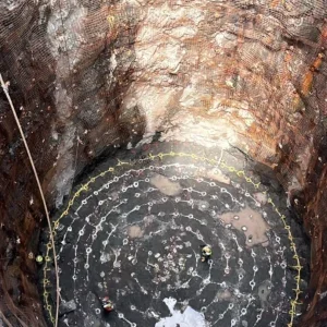
The really radical part was that the risers would be installed from inside the tunnel. Each would be pushed up through a hole in the crown and then through the sludge and sediments of the estuary bed (the bottom part of the riser was in very dense sand and this required the use of hydro-demolition), until they penetrated into the estuary itself from below. Nozzles in a hydraulic displacer head at the top of each riser would jet water tangentially to help clear its path; displaced muck, clay and sand exited down a tube inside the riser to the tunnel for removal.
The one-pass solution for the main outflow tunnel reduced construction time and costs, but it also led to significant design challenges. It had to allow a useful life of 100 years, during which access for maintenance would be all but impossible. The 300mm-thick concrete segmental lining gave an internal diameter of 4.3m. Given the internal pressure, these would tend to spread apart radially. A load-sharing scheme between radial bolts and circumferential dowels counters this.
SEALING THE LINING
At each segment joint, two inclined T28 AISI 316L stainless steel bolts with 160mm-long plastic sockets and four high-strength (220kN) shear dowels per segment interact to take tensile axial forces. A sealed-double gasket system gives high water tightness. The outer gasket is coupled with a continuous hydrophilic gasket; a hydrophilic strip is also fitted in the circumferential joint to prevent water flow inside both gaskets during construction stages.
The very few one-pass segmental lining solutions that have been built so far have relied on complex joint or segment arrangements to give adequate strength in tension. The Riachuelo design is very much simpler.
As well as the significant cost and time savings – reducing quantities of construction materials and slashing two years from the construction time – the single-pass solution also gives a larger-diameter tunnel, since no space is taken by a secondary lining. This brought further savings in the form of greater capacity, allowing the finished scheme to carry 27m3/s rather than the originally-specified 24m3/s of effluent.
At the far end of the tunnel, the revised design dispenses with the vertical transmission shaft, the shallow diffuser pipe, and the 35m-deep piles on the estuary-bed which would have supported it. All of these would have needed considerable offshore work.
“There are many complications with offshore work” says Nicola Valiante, lead engineer for Webuild on the project. “Apart from the cost, and the risk, there are navigational considerations, and weather conditions can halt work. Even scheduling offshore is problematic. So we were looking to improve on that solution, and to mitigate risk. The opportunity to eliminate the offshore shaft and to make direct connections to the risers from inside the tunnel removed almost all the need for offshore work.”
LAUNCH SHAFT
The outfall tunnel begins at four large onshore shafts, of reinforced concrete diaphragm walls, each with a diameter of 14m and around 50m in depth. These were excavated in dry and then in underwater conditions; a 3m-thick concrete bottom plug, also poured in underwater conditions, prevented risk of failure of the bottom of the excavation. The shaft was finally emptied and a permanent 1.5m-thick bottom slab could be cast.
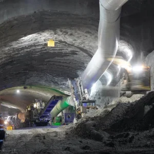
This resulting cavern will provide the hydraulic pressure head that will ensure effluent flow. It also served as the launching pit for the TBM, a Herrenknecht 5.2m-diameter EPB machine. Excavation was under 4bar pressure. No cutterhead changes or hyperbaric interventions by operators were needed during the 12km dig.
“We put video cameras on arms into the cutterhead space to monitor the condition of the cutter heads,” says Valiante, “which showed us that there was no need for that.’ At the end of its run, 12km from shore, the TBM was sealed-in and abandoned in situ.
While the tunnel was being excavated Valiante was working on the design and installation procedures for the risers. “My hope was to improve solutions and mitigate risk” he says. “So I investigated ways of placing and connecting the risers from inside the tunnel, to remove the need for offshore work.”
JACKING PIPES VERTICALLY
The solution he came up with dispensed with the offshore vertical shaft, and installed the now-longer vertical risers by pipejacking from inside the main tunnel. “This is something that had never been applied, or as far as I know, even considered, before,” he says. “Pipejacking above ground, horizontally, is of course standard; but not vertically from below the ocean, in geology that is under 4bars of water pressure.”
It had to be got right first time. Improvising solutions 12km from shore in a narrow, blind-ended tunnel in which you are deliberately making 34 holes in the roof is probably not a good idea. “A crucial part was testing our ideas” he says. “We ran a programme to find the most suitable solutions; we spent two years on designing and testing.”
The risers were of steel, again with a 100-year lifespan. As in conventional pipejacking, they were pushed through the roof, one section at a time, by jacks resting on the tunnel floor. When the first section of a riser had been pushed up, the jacks withdrew, the second section was placed between the jacks and the first one, and both were pushed further up. Each section had to be shorter than the diameter of the tunnel. The cycle was repeated, around 19 times with 19 sections, until the first section broke through the estuary bed into the water.
The top of each riser carried a displacer head, a hydraulic excavator to clear its path as it was pushed upwards. Fed by high-pressure water, the head has a grid of 25 nozzles, angled tangentially in various directions to create a swirling vortex. It sweeps the muck into a chamber below it, which more pressure nozzles keep clean, and thence down a pipeline into the tunnel, discharged into tanks and transported by rail wagon along the 12km back to the entrance.
“The seals between the risers and the outflow tunnel had to be redundant and robust. Ingress of water at the end would have been very hard to manage” says Valiante, with some understatement. “The railway we installed to carry people along the tunnel travelled at 10km/hour, so it took more than one hour for workers even to get to the head or back out. So at a very early stage of the project, we were analysing the major risks involved. Everything had to be tested in the most critical conditions before the installation.
“But you cannot test everything at once, so we established a series of tests, of trial and adjust, and trial again. That led to some important changes in design. I was leading the team and I was always thinking: ‘Am I missing something that may jump up and bite me later?’ So, I brought in other colleagues, fresh pairs of eyes from outside the project, for comment. That helped move away from the mindset which maintains that ‘this is the only solution.’
“When you do something innovative you don’t have all the answers at the start. From the prototype you solve problems one by one. This was not an improvement over existing technology: it was something completely new. There were no experts who could tell us of their prior experience.”
The solution that was adopted pushed the risers through specially designed keystones that had been installed as top tunnel segments. “There were 34 of them. We needed the special keystone segments to be precisely at the apex, with very limited tolerance; a major concern was that the TBM might have rotated slightly to change its orientation so we devised a system to ensure accuracy to within just one degree – that was about 30mm, given the diameter of the tunnel.
“The tunnel had to be completed, to its end, before we installed the risers. That meant that the keystone segments were in place for almost a year before the jacking operation that used them. They were installed with the sealing systems and the displacer heads already in place, so the design had to ensure that they would work perfectly, first time, after a year underwater. That was a real concern.
“The sealing system, between the steel risers and the concrete tunnel segments, had to allow the risers to be jacked without leakage, and yet had to fit within the 300mm thickness of the concrete segment walling. It consisted of three lip gaskets, plus two inflatable gaskets for emergency use. (Happily these were never needed). We monitored the pressure at each chamber between them, and the initial riser section had a biaxial inclinometer to monitor the inclination. The whole thing was packed with grease to lower friction.
“One line within the risers carried a discharge pipeline for the excavated muck, three 300bar hydraulic lines for the demolition system and a compressed air line. The grout behind the segments had to be such that it did not interfere with the pipejacking process.
“So it was a very complex system, but in the end a very robust one. We expected to encounter less than 4bar of pressure and designed the gaskets to withstand 6bar; our safety margin worked well.
“To make sure that all of this worked as it should we set up a test rig, in Italy, that reproduced, full-size, all the conditions of the jacking operation. Pressures, numbers of nozzles on the displacer heads, the jacking force and frictional force were all varied and tested to find the optimum. One thing we did discover was the necessity of the hydraulic demolition head; without it, we would have needed a very high jacking force, of 2,000t to push the risers, which was not feasible. The hydraulic demolition reduced the pressure on the displacement head to almost zero, and meant that a jacking force of 400t would be enough – that force was mainly against friction.
“We included in our rig the worst-possible-case scenarios that we might encounter. These included the risers being out of vertical; we tested all the geometries. Above the jack and the reproduced tunnel keystones we had a container of silts and clay representing the estuary bed; one problem in this was reproducing exactly the geologies of Argentina. The lower layer was a sandy material, which caused most of the friction; that first 8m was the hardest to push. On top of that the ground was weak, unconsolidated clay, and very soft.
“Another benefit of the testing rig was that we could train the workforce on it: workers came over from Argentina to practice on it, so that when the real operation took place they were familiar with every aspect.
“Pipejacking availability was a problem: they are available for horizontal pushes but not for vertical ones. Each section of the steel risers weighed 600kg. There were 600 of them in all, so 600 joints between them; the joints, too, had to be specially designed, for fast and simple connection. We settled on a spigot-and-bell design that used ball bearings in grooves, 250 bearings per joint, each one inserted by a dedicated device, with two O-rings to guarantee watertightness.
SUCCESSFUL CONCLUSION
“I am happy to say that all testing and design changes worked. One thing that pleased me most was that the crew on site found the system easy to carry out and effective. It took one day to install each riser, and with 34 risers, and two sets of equipment working simultaneously, that work was completed in under four weeks. When risers were in place, divers went down to replace the displacement heads with the permanent diffuser heads which would pass the effluent into the estuary; that was the only major maritime aspect of the operation.”
The project is nearing completion. A concrete floor is being installed at the end section of the tunnel to allow progressive reduction of its cross-section as the effluent leaves it through the 34 risers.
The single-pass tunnel and the revolutionary vertical pipejacking have delivered improved hydraulic efficiency both during construction and operation of the project, reduced environmental impacts and emissions, and allowed robustness of scheduling through the avoidance of maritime works, which also avoided navigational disruptions. And the project as a whole should deliver vastly improved environmental conditions for the Riachuelo River and the people living alongside it in Buenos Aires.