The London Basin is formed from chalk at the base with a succession of soils above. The chalk is a major water supply aquifer and is recharged at outcrops to the north and south of London. Between 1830 and about 1960, the lower aquifer was over exploited for water supply and this resulted in a big drop in the chalk’s water level. Since then, abstraction has reduced, groundwater levels have risen and are now controlled by managed abstraction for water supply and by construction dewatering. A simplified geological profile in London is shown in figure 1.
The River Terrace Deposits (RTD) above the London Clay form the Upper Aquifer. Below the London Clay, the Lambeth Group channel sands form the intermediate aquifer. The channel sands are frequently bounded above and below by clay with limited distant lateral recharge. This implies the potential for a large distance of influence and relatively limited inflow.
The Thanet Sand forms part of the lower aquifer and is overlain by Lambeth Group clays with a recharge boundary below from the chalk. This means the distance of influence may be limited by recharge from the chalk, and well yields are limited by the low permeability of the Thanet Sand.
The chalk below is the major part of the lower aquifer. Groundwater flow in chalk is predominantly via joints. Pumping from the chalk underdrains the Thanet Sand. The chalk aquifer permeability typically reduces with depth. This implies the potential for a large distance of influence, high flow, and high well-yields. However, flows are dependant on the jointing, and where there is limited or no jointing there may be minimal flow.
CUT-OFF STRATEGY IN RIVER TERRACE DEPOSITS (UPPER AQUIFER)
This strategy was used in the construction of Heathrow Terminal 5 in 2002, and is based on cutting off the groundwater to control inflow to the construction area. The geological sequence at Heathrow is illustrated in figure 2 and as can be seen the excavation in River Terrace Deposits is dry. This was achieved by the presence of a historic slurry wall which was subsequently extended around most of the area of the excavation to provide a cut-off through the River Terrace Deposits into the London Clay. The trapped groundwater within the cut-off was removed by pumping prior to excavation.
ABSTRACTION AND RECHARGE STRATEGY IN RIVER TERRACE DEPOSITS
Where a full cut-off is not feasible, abstraction, sometimes with recharge to the same aquifer, may be an alternative solution. This was the case for the redevelopment of Television Centre in White City, London. This had a listed retained façade and the existing basement was to be deepened. There was limited sewer capacity for discharge and creating a complete cut-off around the structure was not possible. The strategy adopted was to install a sheet pile cut-off around part of the basement and to use internal abstraction wells and external recharge wells (figure 3).
Recharge is an increasingly important aspect of groundwater control schemes because it is an alternative means of disposal, avoiding the cost of discharge to a sewer or the consents required for discharge to surface waters. In the right circumstances, it can provide mitigation for surface settlement or adverse environmental impact.
DEWATERING STRATEGY WHERE THE LONDON CLAY IS NOT PRESENT
At the Tideway CSO at Deptford Church Street, the London Clay and Lambeth Group had been removed by erosion, and excavation was through the River Terrace Deposits to just above the Thanet Sand. A secant pile retraining wall was installed into the Thanet Sand with dewatering from the Thanet Sand to control the inflow under the secant pile. Figure 4 shows the project during excavation with the internal pumped wells clearly visible.
PRESSURE RELIEF STRATEGY IN LONDON CLAY
London Clay is relatively stable and typically does not require dewatering but sometimes pressure relief wells are needed in the strata below to control uplift pressure. This was the case at the auxiliary shaft at Limmo on the Crossrail project.
Here, a 27m-diameter shaft to 40m depth was excavated in London Clay to 5m above the Lambeth Group sands. The strategy was to install nine passive relief wells which leak excess pressure from the underlying sand strata into the excavation, with sump pumping used to remove the inflow. This strategy can be effective for excavations in London Clay with high pressure below.
DEWATERING STRATEGY IN LAMBETH GROUP
The Lambeth Group is predominantly cohesive, and at some locations is entirely cohesive, but contains occasional granular horizons or channel sands. The water-bearing granular horizons in the Lambeth Group range from laminations to channels as little as a couple of meters wide, up to 300m or more in some places, and can vary in thickness from a few millimetres to over 10m.
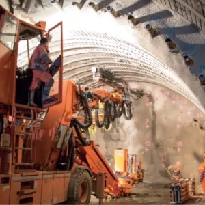
Figure 5 shows an in-shaft dewatering system used for the Tideway shaft at Heathwall. This dewatering system was installed after partial excavation of the shaft to control seepage flows in a Lambeth Group sand horizon in order to facilitate excavation and SCL support for the shaft.
SURFACE DEWATERING VERSUS IN-TUNNEL / IN-SHAFT DEWATERING
Dewatering systems installed from ground surface have the following characteristics:
? Often limited access particularly in congested areas.
? It may be challenging to intercept sand channels or intermittent horizons.
? It is inefficient to install deep wells from the surface with short screen-length. ? Due to the depth, ejectors or submersible pumps are required.
? Well installations are unlikely to be in artesian conditions.
This contrasts with in-tunnel / in-shaft dewatering systems as follows:
? Better access to target horizons (from pilot tunnel or shaft perimeter).
? Systematic probe drilling can be carried out to identify the presence and extent of any sand.
? It is cost effective to install wells at close spacing.
? Well installations may be relatively short.
? Simple and robust vacuum wellpoint systems can be used if drawdown is less than 5m.
? Well installations may be into artesian conditions which require a stuffing box.
A combined surface and in-tunnel/shaft approach, particularly where pore pressures are high, is often the most attractive strategy.
Over the past 30 years, there have been some significant improvements in dewatering equipment for use in tunnels and shafts. Initially, it was common to use surface equipment below ground but now, more compact specialist equipment for in-tunnelling and shaft dewatering is available. This has now come full circle with in-tunnel equipment and techniques being applied to various surface installations at congested urban sites.
DEWATERING STRATEGY IN THE THANET SAND
The Thanet Sand and chalk below are typically in hydraulic connection so that groundwater lowering can be achieved either by pumping from the chalk and under-draining the Thanet Sand or by pumping directly from the Thanet Sand. Pumping from the chalk may generate high flows and a large distance of influence but can be necessary where a significant drawdown is required. Conversely, pumping directly from the Thanet Sand involves lower flows with localised impact but limited drawdown.
The Crossrail Limmo Main Drive Shaft was 30m in diameter with an excavation depth to 44m. Side support was by diaphragm walls which provided full cut-off through the River Terrace Deposits and Lambeth Group Channel Sands. Pressure relief in the Thanet Sand was needed to construct the base slab with a reduced requirement during the remainder of the tunnel drive construction period. The required drawdown in the Thanet Sand was achieved using the well array illustrated in figure 6.
Following excavation and construction of the primary base slab, pumping from the chalk and external Thanet Sand wells stopped, and only the internal Thanet Sand wells were operated passively to provide sufficient pressure relief. After completion of the tunnelling drives, the secondary base slab, lining walls and roof were completed and then the internal Thanet wells were decommissioned. Total flow during the eight-month shaft excavation and primary base-slab construction period was 160 lit/ sec, achieving a drawdown of approximately 30m in the Thanet Sand, with most of the flow derived from the chalk. For the remaining two-year tunnelling period, the flow was reduced to 10 lit/sec from the Thanet Sand only, achieving approximately 10m drawdown in the Thanet Sand.
DEWATERING STRATEGY IN CHALK
For the chalk in London below the Thanet Sand, much of the significant jointing is near horizontal so that the local vertical permeability can be two or three times lower than the horizontal permeability. At depth, the overburden stress appears to close many of the fissures and joints resulting in a significant reduction in permeability with depth. Chalk is also soluble so that water flow can enlarge joints and enhance flow over geological time.
This setting has led to the development of the following strategy for deep shafts which reach into water-bearing chalk:
1. Prior to shaft construction, install a chalk well within the footprint of the shaft and undertake a pump test and geophysical logging.
2. Use the data from the pumping test to review the depth of the diaphragm wall or other cut-off planned for the works. Numerical modelling may be undertaken to assess inflows.
3. Install the diaphragm wall or other cut-offs.
4. Install a second chalk well within the footprint of the shaft and repeat the pump test to assess inflows. Note that at least two installations are required, so that one can be pumped, and the groundwater level monitored in the other.
Where there is a hard limit on abstraction flow rates or external drawdown, this strategy requires contingency measures, such as a grout curtain or base grouting to be available if flows or drawdowns risk exceeding any constraints.