INTRODUCTION
The £700 million Bank Station Capacity Upgrade (BSCU) was completed in February 2023, creating 40% more capacity, easier interchange between lines, step-free access to the Northern Line and a new entrance and ticket hall on Cannon Street. The once much maligned station, with convoluted routes joining the Circle and District, Northern, Central, Waterloo & City lines and the Docklands Light Railway (DLR) is now easier to use and popular with its customers.
Much has been written about the innovative contractor engagement procurement process (e.g., Jensen, 2015) that London Underground (LU) applied before awarding Dragados SA an NEC3 Engineering and Construction Contract Option C to design and build the upgrade, in 2013. In summary, the Dragados team, including Dr Sauer & Partners (DSP), were proposing a scheme that yielded substantial benefit over the base design in several areas and improved the benefit-cost ratio by 45%. But the innovations did not stop after procurement. This article looks to highlight some of the developments during the design and construction stages that followed, and points to where further details can be found.
The BSCU project is one of the major underground projects in London that was developed after the design, and much of the construction, of Crossrail. Crossrail undoubtedly progressed expertise in sprayed concrete lining (SCL) tunnelling in the UK, and also generated and shared lots of lessons for future projects to learn from. We have therefore used it as a baseline a number of times in the following review.

The DSP team on BSCU were initially responsible for design of the SCL tunnels within a wider multidisciplinary design team lead by URS. As the project developed beyond scheme design, Dragados became the principal designer, leading a group of specialist smaller design companies, including Robert Bird Group, GCG, OtB and DSP looking at the underground structures. The Dragados Construction and Engineering teams worked directly with these specialists to innovate and identify efficiencies on cost, carbon, programme and to improve safety during construction. Now, a year after project completion, we look back on what was achieved, where lessons can be applied elsewhere and what could be done better next time.


SCL – LINING SYSTEM
On BSCU, similarly to Crossrail, both primary (PL) and secondary (SL) linings carry the permanent loads; assuming a combined interaction between the lining components rather than composite action. However, unlike Crossrail, the proportion of the long-term ground load taken by the primary lining was not prescribed in standards prepared before design began. Instead, the load share between the primary and secondary linings was the outcome of a three-dimensional numerical analysis, resulting in significant reductions in thickness. Initially, a double-bonded spray-applied waterproofing membrane sandwiched between the linings was adopted for the whole project.
Each waterproofing option has its own pros and cons with respect to constructability. However, from a structural designer’s point of view the main difference is that when using a sprayed membrane, groundwater migration between the linings is very unlikely and it can be assumed that both linings move together under the long-term load condition. This scenario can save on overall lining thickness as the secondary lining load cases are reduced. In a sheet membrane scenario, water can potentially migrate between the linings and find its way all around the tunnel cross section, applying full hydrostatic pressure on the SL. In some tunnels the design did switch to a sheet membrane system with cast SL, to be installed using a travelling shutter that could produce a smooth finish. In locations with consistent geometry, that would be exposed to the public, this was found to be more efficient for cost and programme purposes. The cost savings were in part related to a more efficient use of materials and resulted in a carbon reduction through greater replacement of CEM 1, as well as lower wastage.

As Dimmock (2022) rightly stated: zero carbon tunnelling should start from efficient, state of the art design, even when carbon reduction has not been set as a specific target. Designers should be flexible to differing requirements in different locations, but equally requirements should be easy to keep up-to-date and justifiable as technology evolves. Setting a sensible set of design principles is key if we wish to have efficient linings and reduce tunnelling’s carbon footprint. Obviously, these principles should be tailored to the specific conditions of the project and need to be agreed with the client and the CAT 3 checker. LU tunnelling standards avoid prescribing design items but allow for efficiencies to be found to suit the circumstances. Principles are set during scheme design; when information is available to make informed choices.
Design assumptions for BSCU include:
- Despite being located outside the waterproofing membrane, the PL is considered to be durable and part of the permanent support. A durable PL was credible due to unaggressive ground /groundwater condition revealed from chemical tests in addition to extensive knowledge of material behaviour in London Clay. A 75mm sacrificial layer outside the primary lining, as applied across the Crossrail route, was not considered to be required.
- Considering a 5-year design life for the PL during construction allowed us to use a lower load partial factor (1.2) for the temporary loading cases than the permanent load partial factor (1.4 in LU Standard S1055) prior to installation of the SL. This led to a leaner PL thickness without compromising the overall support for a 120-year design life.
- Non-linear analysis of the fibre reinforced concrete lining was allowed. No crack width criterion was set for the serviceability limit state of the SL as the tunnels were assumed to be fully tanked inside the waterproof membranes and the publicly accessible areas in the station are clad. This led to design of the PL/SL without rebar, except L-bars at tunnel junctions to assure connectivity between the child/ parent tunnel. Relaxing crack width requirements in the industry is becoming more common (Norrish 2023).
- A minimum thickness of 150mm was set for the fibre reinforced SL to prevent penetration of the tunnel fixings to the waterproofing membrane (max 100mm embedment for fixings considered).
- The minimum period of fire resistance of the tunnel lining is 90 minutes. According to the tabular method of concrete design against fire in EC2 the lining thickness must be minimum 140mm, which is less than the 150mm minimum thickness chosen for the SL. The fire design strategy was to assume the SL a sacrificial layer.
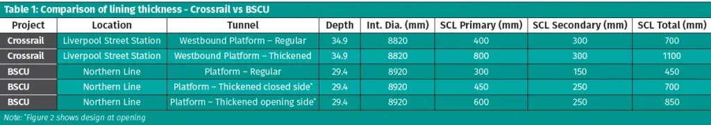
By applying the above principles, the design of SCL tunnels on BSCU used a leaner lining system in comparison with Crossrail, with a similar SFRC lining specification. Table 1 compares lining thicknesses of a platform size tunnel at Bank versus Crossrail Liverpool Station. It is observed that a 35% reduction in the overall lining thickness and up to 50% reduction in the secondary lining has been achieved. No rebar in the lining reduces the carbon footprint even further. At T-junctions, thickenings were localised to the opening side with a simple step in the tunnel lining at crown and invert (see Figure 2). A small change, but every little saving in the design helps. For further details refer to Nasekhian & Feiersinger (2019), which highlights the design considerations for different components of the combined lining.
RADIAL JOINTS
One of the areas of SCL tunnelling that Crossrail had worked hard to improve was management of exclusion zones and safety of the site team, particularly when working with open ground and freshly applied concrete (Anthony 2020). Both the design and construction team on BSCU wanted to build on this; with an area to address being the need for the tunnelling team to enter the face to install radial bars to connect top heading to bench excavations, or benches to inverts. The resulting radial joint system requires care and supervision, but can be fully mechanically excavated, meaning that no one needs to enter the tunnel face at any point in a standard tunnelling cycle. This removes the waiting times that have to be managed before Kwika-strip installation etc, and so not only made exclusion zone management simpler (the face is out of bounds all of the time), but also sped up the excavation process, so was considered a win-win.

The team of tunnel inspectors were also happy with this approach and it has been applied on other LU projects since, with similar success. One of the other benefits of removing person entry into the tunnel face is that the thickness of material applied to stabilise it does not have to be dictated, but can be sufficient to prevent the ground ravelling or drying out before the next advance, when it will be removed. A thicker layer of material on the face is only needed for extended shut-downs.

ASSESSMENT OF IMPACT TO LU EXISTING ASSETS
In addition to design of the SCL tunnels, DSP carried out impact assessment of tunnelling works on the existing LU Civil assets. Combining both tasks under one team ensured an integrated design solution that considered asset protection and efficient design together. It also resulted in significant time and cost saving.
Adopting the staged approach from the LU standard S1050 and working closely with LU to benefit from their knowledge of the behaviour of their assets, the assessment process was as efficient as possible; allowing focus to be directed to the assets where movements will have the greatest impact. Only the most relevant tunnels and openings were incorporated into the 3D Finite Element Analysis (FEA) models that were created to design the new structures; maximising the benefits of this computational effort and creating a more complete and interrelated model than has been used previously.
Using this combined model LU, DSP and Dragados had more confidence in the predictions and could update models during construction based on measured movements in a way that can be clearly traced and interrogated. In conjunction with focussed assessment, a joined-up monitoring and inspection plan was used to address any outstanding risks, learning lessons from previous LU upgrade projects to address serviceability impacts that monitoring alone struggles to capture.
From an initial list of 287 civil assets at Bank, only 13 indirectly affected locations required strengthening to withstand the changes in loading and deformation to them, despite the substantial tunnelling planned around the operational railway. With greater understanding of the anticipated movements, it was possible to avoid expensive and intrusive mitigation measures that would impact the travelling public, such as propping, jacking of escalators and speed restrictions.
TUNNEL CONNECTIONS
At the concept design stage all proposed tunnel connections to the existing infrastructure were designed using traditional hand mined tunnelling methodologies (also referred to as squareworks). There were four SCL cross passages, connecting to the trackside of the 6.5m-diameter existing Northern Line southbound platform tunnel using squareworks openings. This included two 12-ring (cross passages 1 and 2), one 10-ring (cross passage 3) and one 7-ring wide (cross passage 4) openings. The width of each cast iron ring is 457mm. A further three adits located between the platforms were designed to be constructed using handmining.

The squareworks designer at concept was concerned about failure of the existing cast iron tunnel due to ground movement induced by the new works and propagation of tensile cracks within the tunnel segments in and around the bolt holes and through the depth of the segment pans. The Northern Line connections were identified as requiring extensive strengthening works prior to the tunnelling, noting that internal propping in the platform was not an option as the platform had to be kept operational during construction and was already highly congested.
The mitigation proposed a series of steel segment pans that would sit within the existing cast iron segments just around the openings, to be connected using new bolts through the existing holes. The existing cast iron pans on the Northern Line platforms are infilled with plain concrete, which would have to be removed to install the stiffeners. Clearing the pans in the operational platform tunnel in advance of constructing the cross passages (and adits between the platforms) would have required significant enabling works with notable programme and cost implications.

During later design stages, DSP undertook detailed analyses at each connection to assess the impact on the existing cast iron segmental rings and concluded that the lining stability would be maintained through all stages of formation of the openings in the existing tunnels. LU agreed that a concession against Standards would be acceptable to allow local overstress of the existing cast iron linings, i.e., local cracking close to the openings could be tolerated so long as overall stability of the existing linings was demonstrated. This was because of the operational constraints on installation of in-tunnel propping, the risk of damaging the cast iron by removing the concrete to install the steel pans, and that damage in both those mitigation scenarios might just be delayed or transferred farther down the tunnel.
The proposal was that measures to address any localised serviceability issues would be delayed until after construction of the connections, i.e., if cracking in the cast iron segments occurred it would be repaired. Risks were thoroughly managed through the monitoring, inspection and watchperson measures in place, all managed through the Required Excavation & Support Sheet (RESS) process as normal.

In the end, three out of four squarework connections at the Northern Line level were replaced by an SCL approach at the detailed design stage. Cross passage 4 (CP4), the smallest opening (3.3m wide), was built first. No cracking was observed in the existing cast iron segments from the connection, though one pan was damaged due to concrete removal at a later time. For more details see Nasekhian et al. (2020).
Next, construction of the largest SCL connections (CP1 & 2) took place. Their final opening width was reduced to 10 rings from 12, but were still anticipated to pose a higher risk of localised damage to the cast iron segments due to the relative size of the excavation to the existing asset. An 8.4m-wide SCL passage approached the platform perpendicularly, with a sequence of two top-headings followed by bench and invert (see Figure 5). Cracks occurred in the cast iron flanges at the shoulder and near crown level above the openings during the top-heading/bench excavation, as predicted by the assessment. From their initial appearance they were monitored. Rigidity provided by connection of the SCL lining to the existing tunnel restricted further distortion of the cast iron rings and excavation was concluded without any issues.

The final cross passage, also 10 rings wide, was constructed using squarework techniques. Similar cracking to that in CP2 was seen in the existing tunnel, illustrating that the methodology was not the deciding factor, but rather the size/width. While there was no risk of collapse (using either methodology), and the repairs were successful, it is recommended that the parent/child relationship in future projects is considered carefully. For upgrade works, this is normally limited by the dimensions of existing tunnels. Given that permanent props are not an option in many cases (and damage is merely delayed to the moment of removal of temporary props in many others) the number of rings in an opening should ideally be chosen such that the parent/child ratio is greater than one.
Two of the adits between the Northern Line platforms, and the five connections to the DLR, located below the Northern Line, were similarly transferred from a squareworks to an SCL/hybrid SCL methodology. Due to the complexity of connections to the existing assets, which are composed of a variety of materials including pre-1900 cast iron segments, precast concrete segments from the 1990s, brick arched passages, and mass concrete collars, 3D analysis was employed to deliver the assessment of these connections. Pamsl & Nasekhian (2023) and Nasekhian et al. (2023) presented numerical modelling predictions versus the existing assets responses due to SCL connections. Unlike the Northern Line cross passages, for these connections access was from above. It was found that early stabilisation of the assets using a frame or concrete collar minimised movement of the segmental linings.

PILE INTERCEPTION
The BSCU scheme necessitated a new section of Northern Line running tunnel that needed to tie into the existing line at each end. At the early stage of the design, nine buildings along the potential route were identified as having a deep foundation, with a risk of either being intercepted or passing close enough to the new tunnel to transmit noise to the building above. It was sadly impossible to avoid all deep foundations without compromising the scheme. Therefore, the track alignment was designed considering the requirements of train speed and track maintenance while also trying to minimise pile interceptions. The final alignment intercepted 26 piles (friction and end bearing), either fully or partially.

The most critical case was an unavoidable pile interception of a nine-storey building with two basements (concrete structure built in the 1970s) at the Northern tie-in. The tunnel route constraints were such that even after optimisation the tunnel fully intercepted four out of 25 end bearing unreinforced concrete piles (shaft diameters ranging from 1.5m to 1.8m) and partially intercepted seven others. A major requirement for the project was to minimise the impact of tunnelling on the piles and retain the capacity required for an additional two floors to be added to the building if it underwent future development. The assessment undertaken to understand the impacts of tunnelling on the building was one of the most challenging parts of the project.
The building owner’s technical representative needed to be sufficiently convinced that the proposed construction sequence (cutting the piles first and then supporting them on a load transfer structure) would not cause the building to exceed the damage criteria agreed. To demonstrate this, a comprehensive soil-structure interaction was undertaken using 3D FEA (see Figure 7). The ground model developed by DSP included the pile-raft foundation, building basement and all tunnel excavation sequences. It was coupled with a superstructure model created by Robert Bird Group to assess the building response due to the tunnellinginduced settlements given by the substructure model. Nasekhian et al. (2021) gives a detailed account.

In addition to the complex modelling, TfL and the contractor Dragados approached Cambridge Centre for Smart Infrastructure and Construction (CSIC) to install a highly innovative system to monitor the piles in the building in real time. Understanding the responses of intercepted piles due to tunnelling is crucial, yet very limited case histories have been reported, mainly because of the difficulty associated with deploying conventional instrumentation in existing piles.
On BSCU, distributed fibre optic sensors were installed into two existing large-diameter 25m-long end bearing piles – one intercepted fully and one partially by the 6.5m diameter running tunnel. The sensors were used to monitor behaviour during tunnelling, pile interception, transfer structure installation and post construction. The use of fibre optics to measure strain in the piled foundations was an important aspect in the verification of the design of the pile interceptions. Barker et al. (2020) provides further details. It is believed to be only the second project in the UK to use optical fibre instrumentation to observe the behaviour of existing piles for reuse and the first project for piling interception for a tunnelling project.

UPHILL EXCAVATION OF AN INCLINED BARREL
A new triple escalator now travels between the Central Line platform tunnels, improving the connection to the Northern Line and facilitating faster interchange between the different parts of the station. Unusually, the inclined escalator tunnel was excavated uphill rather than downhill due to restricted access (see Figure 9). Uphill escalators had been built on Crossrail, but in this case there was insufficient room for a pilot tunnel to repeat their methodology. The new escalator also intercepted several existing structures that had to be backfilled and then broken out, some just 0.5m from operational platforms. Kumpfmueller et al. (2022) report the design considerations, construction sequence decisions and operational risk management, and discuss the existing assets’ response to uphill tunnelling based on a comprehensive monitoring scheme.

LESSONS LEARNT
In addition to the items described above, some of the further lessons learnt during the works on BSCU included:
- Maximising the use of mechanical excavation doesn’t have to increase the risk of damage to existing assets. During the early design stages the basis of using hand-mining techniques to excavate the connections to existing assets was in part based on perceived risk of an excavator damaging the brittle cast iron. The repeated excavations up to, over and around existing assets on BSCU, all while trains and passengers safely continued usage within, were managed using sensible mitigation measures such as toothless buckets, probing/measuring ahead, watchmen inside the platforms, and good communication of the risks to all involved.
- Depending on the scale, you don’t have to commit early to one waterproofing system throughout a project, but should manage the decision-making process on a tunnel by tunnel basis in conjunction with the construction team. While local areas of complexity might suit the adaptability and lining efficiency potential of a sprayed system, relatively long straight tunnels within a complex system might still be optimally constructed using a sheet membrane approach and merit the initial expense of a shutter.
- Opening frame designs can be optimised using high strength steel to reduce the size of members, making them easier to transport to their required location and simplifying lifting plans. Reinforced concrete solutions can have further benefits where the route to the opening is not readily accessible or the space to install opening support is limited. Where existing assets are not well aligned, reinforcement is also better able to adapt and doesn’t require shims, etc.
- Connections to existing tunnels are still an area of significant unknowns, where levels of conservatism can be overlain, potentially reducing efficiency and creating other risks. Assuming full over burden loads on the new openings typically results in heavy/large steel beams, which pose significant health and safety risks during construction, but limited data exist to justify moving away from this approach. Strain gauges were installed on the opening beams of one of the largest openings in the Northern Line platform to share knowledge for future projects. More projects should install strain gauges to understand opening frame behaviour and loading from the cut segments. While they won’t necessarily help the project you are on, a data set is needed to allow future optimisation.
- There is a balance to be struck between constructability and carbon savings. Practical minimum thicknesses for cast secondary linings may limit the potential to optimise these secondary linings but can still result in lower CO2 than a sprayed solution when taking into account lower wastage values, rebound, not requiring additional regulating layers and even the potential to avoid cladding. Tools to quickly compare options need to be standardised across the industry to allow decision making and reporting on a fair basis.
BSCU won multiple awards over the project’s lifetime, but most significantly for many involved in the project, a number of those recognised the importance of the behaviours of the team. This includes winning the NCE Tunnelling Team of the Year, twice, and the BGA’s Fleming award, which emphasises teamwork. Many of the improvements in design and innovations discussed above were the direct result of the open lines of communication available between the client, design and construction teams. Co-location is most definitely a part of this success, but equally important was the mentality and approach from all involved. In complex upgrades, having asset owners that understand their assets and are well resourced to manage risk in-house, as well as having mature standards that maintain requirements without inhibiting innovation, are as crucial as knowledgeable construction and design teams. On BSCU we were lucky to have all these things and hope that future projects are as fortunate as we were.