and Choi, 2012). Since that time the author has found the method to be very practical and useful and the guideline has been implemented in many tunnel security design practice. As the blast protective design was being performed, however, up to date approach and methodology have been added into the guideline. The new proposed guideline is intended to clearly explain how to assess the risk and vulnerability, how to analyse the blast impact on the structures including progressive failure potential identification, and to present the latest developed tunnel blast protection measures. ¬
The protective design of tunnels consists of identification of the potential threats to the underground facility, evaluation of its vulnerability and risk level, analysing the impact of internal and external threats on its assets and providing internal and/or external structural hardening measures, and finally cost-benefit analysis. The guideline presented in this paper relies on credible information gathering and the use of proven methods that have been successfully applied to and accepted in the tunnel design practice in USA.
Threat and vulnerability risk assessment
The proposed threat and vulnerability risk assessment includes four stages: (1) identification of project assets and threats, (2) development of threatasset matrix, (3) risk assessment, (4) set priority. The purpose of the threat and vulnerability/risk assessment is (1) to provide safety and security guidelines to identify principal vulnerabilities of assets to various hazards and threats and (2) to provide input data to be employed for the subsequent blast analysis, expressed in terms of threat locations, design basis threats (charge weights), and tolerable tunnel damage level.
The threat profiles for the given tunnel should be compelled enough to include the requirement to elevate the security program to include special counter terrorism design measures. This is in addition to design provisions for conventional security responses for traditional crimes against persons and property, which require routine response and security management. Project site development characteristics and threat assessment considerations that affect the project profiles are then summarised. These characteristics are inherent in the project as a result of its critical transportation function, location, occupancy and connection to adjacent transportation systems. Five major categories of the intentional threats to tunnel structures are vehicle bomb threat, waterborne threat, fire threat, cyber threat, and sabotage of mechanical, electrical and communication system.
The threat-asset matrix identifies each asset and the corresponding general threat scenario that was evaluated and scored. This is accomplished by individually evaluating each asset on the basis of its location within the project, program of use, adjacent structures, occupancies and activities.
The next step is to quantify the risk to the various assets as a function of three factors including criticality, vulnerability and consequences. This approach follows the same basic approach as that used in conventional risk assessment and analysis. Criticality is a measure of the importance of the asset. Criticality identifies which assets within the tunnel system are relatively more important to protect from attack. Vulnerability is a measure of how likely the asset is to be attacked successfully by a given threat. Vulnerability identifies which threats to which assets are relatively more likely to occur. Consequences are a measure of the effects if the given threat is successfully carried out against the asset. Consequences identify which threats at which assets are relatively more detrimental. For each asset-threat combination, the single measure of criticality, vulnerability and consequences is taken as the straight average of the attribute scores. Then, the risk can be calculated for the each assetthreat combination. The results of the risk calculation provide a comprehensive, systematic, and rational basis for thoroughly evaluating the risks associated with assets and deciding the most effective means for mitigating these risks. The results provide the road map for developing mitigation strategy alternatives by threat scenario and asset. The risk score enables to prioritise the strengthening of assets and further blast protective design and construction.
Blast and post blast analysis
Prediction of material damage under a dynamic loading is a complex function of several factors such as loading magnitude, loading rate and loading duration. If the material experiences the same magnitude of loading at a different loading rate, the response will be different. The current paper introduces a blast analysis method, which fully incorporates dynamic properties of materials as well as strain rate effects, so that a dynamic structural response could be predicted reliably when the structure was subjected to a blast loading.
Blast analysis
The purpose of the blast analysis is assessment of the structural damage due to threat scenarios and development of economical and simple-to-construct strengthening measure. The first task is to assess and identify the most vulnerable locations along the tunnel alignment and across the cross section. The most vulnerable locations are selected based on tunnel structural integrity, tunnel alignment, tunnel depth, surrounding ground condition and consequences, i.e. potential of progressive failure or collapse of adjacent underground and surface structures. The second task is to develop three-dimensional finite element models based on the provided plans that capture and characterise the behavior of blast pressure propagation and the dynamic interaction of blast pressure and structures. Modelling of all structural components including, but not limited to, tunnel structures, adjacent columns, surrounding ground and adjacent building structures, shall be in accordance with accepted practice for similar type analyses used to identify and assess potential modes of failure and damage levels. The third task is to perform three-dimensional nonlinear, coupled Euler-Lagrange blast analyses to identify the extent of damage under the postulated blast threat scenarios and selected detonation points. Of particular concern is damage assessment to tunnel structures and progressive type failure or collapse of the tunnel structures and adjacent underground and surface structures including buildings. Finally, the fourth task is to develop strengthening measures and to conduct blast analysis to verify effectiveness of the measures. A simple cost-benefit analysis will be conducted to select the most economical, easy-to-construct strengthening measure for the project.
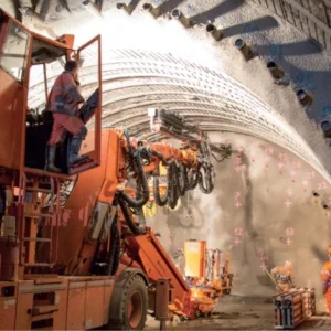
Bored/Mined Tunnels
In cases where a tunnel is located in significant depth or overlying structures exist above the tunnel alignment, bored or mined underground tunnel construction is typically the preferred. The bored tunnel structures are usually composed of concrete. Even though the ballast fill concrete and concrete walk benches provide some cushion against an interior blast, due to the brittle nature of concrete materials, the bored tunnel is likely to be very vulnerable to an interior blast as well as an external blast set from the shipping channel bed. When the tunnels are underneath the water body, cracking or failure of the concrete liner may allow inundation with water and resulting in high flooding potential in the transportation system if the tunnel is connected to underground transportation network. When the ground stability is not preserved, a failure of tunnel liner would impact adjacent surface and underground structures. When segmented precast concrete lining is used, the behavior of the lining is also of concern. Three dimensional blast analysis enables to model behavior of bolted segment to investigate the performance of the segments when they are subjected to internal blast loads and to recommend a proper dimension and number of bolts to be used.
Cut and cover tunnels
Shallow depth tunnels in land are frequently designed using the cut and cover method. This technique involves braced, trench-type excavation and placement of fill materials over the finished structure. The excavation is typically rectangular in cross section in relatively shallow depth. It is likely that the cut and cover sections of the tunnels will be extremely vulnerable to an interior blast due to less confinement from surrounding ground. However, it is probable that the cut and cover sections will be less vulnerable to a surface blast due to the open-air nature of the blast and soil cover over the tunnel. For U-tunnel section, where the tunnel structure is open and not covered, the vulnerability will be extremely high due to relatively easy delivery method of explosives.
Immersed tube
Immersed tube tunnels are employed to traverse a body of water. The tunnel construction method involves (1) construction of tunnel sections in an offsite casting or fabrication facility that are finished with bulkheads and transported to the tunnel site; (2) placement of the sections in a pre-excavated trench, jointing and connecting together and ballasting/ anchoring; and (3) removal of temporary bulkheads and backfilling the excavation. The top of the tunnel should be at least 5ft (1.5m) below the original bottom to allow for an adequate protective backfill. The typical immersed tubes consist of concrete liner, steel shell and concrete tube. The concrete liner and concrete tubes are load bearing elements, while the steel shell is usually not considered to be a load bearing element but rather acts as a waterproofing membrane. The joints between segments may be the most vulnerable if it is not covered with tremie concrete. Local breach of the main tunnel structures would induce complete inundation with water and cause flooding in the underground transportation system. Flooding may also introduce large quantities of sand, silt, gravel or shear zone debris. Significant lengths of tunnel can become filled with debris or backfill in a short period of time. For this reason, the immersed tube structures are considered to be the most vulnerable elements.
Underground stations
The underground stations are constructed by either cutand- cover method or bored/mined. Considering high level of access, exposed population and consequences, the station structures are likely to be very vulnerable to an interior blast. For the underground stations, hand-carried satchel bombs and suitcase bombs are the predominant mode of explosive attack, while subway storage yards, service facilities, and the shipping channels above the tunnels allow for the potential delivery of much larger explosive/incendiary materials.
Ventilation shafts
Ventilation shafts are typically reinforced concrete shafts extended from the land surface. At the interface of the shafts and the bored tunnel, they may be more vulnerable to damage because high stress concentrations may occur at these junctions. However, due to access restrictions, only a small amount of explosive is likely to be brought into the shafts, therefore an interior threat within the emergency exit shafts is not considered critical. A more critical threat would be one introduced to the external detonation that large amount of explosives are carried by vehicle.
Cross passageways
The cross passageways may be vulnerable to damage because high stress concentrations may occur at the junctions with main tunnels and given the same amount of explosive charge, the resulting blast peak pressure in a cross passageway tunnel may be greater than that in the main tunnel due to its smaller cross-sectional geometry. However, from an operational standpoint, the cross passageways are not considered to be more critical than the main tunnel elements because of their greater degree of redundancy due to a number of cross passageways. Furthermore, local failure or collapse of one or more of the cross passageway tunnels may not necessarily affect the stability of the main tunnels or prevent their continuous use if the water inflow is controlled.
Portal
From a stability standpoint, the tunnel portal area is generally one of the critical locations due to the inherent slope stability problem and/or retaining structure failure. Tunnel portals are therefore considered to be particularly vulnerable during extreme events. Nevertheless, the consequences of a portal failure are generally considered to be less severe than those of main tunnel element failures because the repair can be done in an open space. The flooding is not an issue when a portal is damaged or collapses, so the repair time and associated costs are relatively low compared to the other parts of the tunnel. Furthermore, at the portal, the blast is less confined and the energy dissipates away rapidly than it will in the confined tunnel environment.
Post blast analysis: progressive collapse and flood potential
In addition to the evaluation of damage extents caused by the blast-induced loading, post-blast behavior should be analysed to evaluate progressive type failure/collapse where continued failure may occur due to the structural weakening, load redistribution, excessive displacements, water inflow or running ground into the tunnel.
Progressive collapse of underground structures is of great concern, even if the underground structural elements are not completely damaged during the blast. They may be weakened or softened, at which point the normal loading imparted during operations would cause further damage or failure to the structures. The progressive failure analyses consider the structure in operation, subsequent to the blast loading. The post blast progressive collapse analysis is performed in such a way, where the damaged area(s) are removed and by applying load combinations to the structures. The segmental lined tunnel is loaded by surrounding ground and water pressure. The complex underground station is assumed to be fully loaded with trains on each track level, with the mezzanine level and platforms assumed to be fully occupied with the full live load and dead load expected.
The stability of the ground is also of concern with the breach failure of the liner when the stability of surrounding ground is not preserved. For soft ground tunnels under water, ground failure and subsequent flowing condition into the tunnel associated with the breached concrete liner failure is a more likely scenario. This ground failure and/or flowing condition may result in large water inflow because of the high water pressure and infinite water supply.
Damage level
The damage levels for each blast analysis are assigned after evaluating the damaged area, determining the remedial construction activities that would be required to return the tunnel to its normal operating condition. Consequences including flooding potential, ground stability, and progressive failure or collapse are also considered in the designation of damage level. In the protective design or strengthening of tunnel structures, it is reasonable to accept a moderate level of damage to the tunnel elements such that disruptions to operations would be limited to a short period of time. Such a level of damage acceptance may result in greater affordability of the tunnel construction cost.
Blast protection measures
During a blast loading, the structures make an attempt to balance the kinetic energy from the blast with the strain energy of the structural members. If the kinetic energy from the blast is greater than the total strain energy of a structural member, the structural member will be breached. The total strain energy is a function of the area under the stress-strain curve of a material used to make up that structural member. Thus, ductile materials can absorb more blast energy. Various products have been proposed in the market for blast protection of the structures. The most common products used in the protective design are summarised (Choi 2012).
Cost benefit analysis
The last stage of the blast protective design is the cost-benefit analysis. The cost-benefit analysis is a systematic approach to the problem of choosing the best method of allocating scarce resources to achieve a given objective. The cost-benefit analysis includes four stages; (1) defining an objective or need, (2) identifying blast protection measures, (3) estimating the costs and benefits of each blast protection measures, and (4) recommending a preferred solution.
Conclusions
Tunnel safety and security require the systematic application of engineering, technology, and management tools to identify, analyze, and control hazards and vulnerabilities within operational, budget and time constraints. This security can be enhanced through a comprehensive process ranging from vulnerability assessment to implementation of remedial measures. They encompass all of the integral factors that comprise a tunnel, including people, operating procedures, systems and controls and the physical aspects of the tunnel components
Questions from the floor
David Gullick, Parsons Brinckerhoff asked how the size of charge was decided.
Choi responded that sizes are usually decided by security personnel who establish threat scenarios where methodologies as to how certain charges can be applied to the structure are developed and charge size comes out of this. The actual size of charge used is classified but it is usually in the order of something that can be carried by a Transit sized van. Backpack sized charges are also used in the modelling.
Guy Lance, consultant asked about the statistics used in the presentation, and were they based on worldwide data or just USA. Also what was the chosen definition of a terrorist.
Choi said worldwide statistics have been shown. The definition is out of the presenter’s knowledge and control. PB usually works closely with security personnel and specialists working for the authorities. PB’s own security advisors are usually retired US Navy or US Army and these people define the terrorist and this is developed into an input for the models.
Lance asked if it be true to say that Choi defines the solution and not the problem.
Choi confirms.
Myles O’Reilly, retired asked what the actual number of incidences where infrastructure has been damaged by terrorism is. He adds that the presentation only refers to percentages.
Choi said statistics in the presentation show that of the several hundred recorded terrorist attacks about 5 per cent have been targeted on infrastructure over the last 50 or so years.
Andrew Smith, Joseph Gallagher said the presentation had been concerned about the design for explosion, but there is also a need to design against a catastrophic fire. He asked if the design for one compromise the design for the other.
Choi said the design loads for each are very different. We a looking for a design that can cope with fire, explosion and also earthquake loads. Blast loads occur over a few milliseconds, while earthquake loads occur over a longer timeframe, but the design for one can assist in the design of the other. In the past design has been done separately for each item by separate specialists resulting in very thick lining designs. In the future they are working towards merging each extreme load into a single solution and research is currently being undertaken to find a material resistant to all three design cases.
Steve Psomas, Morgan Sindall asked how the level of damage is assessed for DUCON (ductile concrete) and if the model was based on strain criteria.
Choi responded that the models are validated using explosion tests on materials to assess actual damage from a given charge on the modelled material. The models are based on strain as this works better than stress although this leads to lengthy analysis times, often in excess of 24 hours.
Neville Harrison, consultant pointed out that there is experience where an accident in a cast iron lined tunnel caused a blast pressure of 9 bars and no damage to the lining was sustained.
Choi said that this was a small blast load. A backpack sized charge could give rise to a pressure 20 times greater than this and it is possible local damage to cast iron linings will occur depending on where the charges are positioned in relation to the lining. The examples presented look more at charges carried in a van and issues related to road tunnels where such charges could be transported into position where damage would be greater.
Will Wholey, TPS Consult asked how the model that considered a blast on the seabed above the tunnel was validated.
Choi said blast loads to concrete, steel and ground are well defined and are consistent with the crater sizes established in field tests. Blast waves through ground were studied in Newmark’s paper in 1963 and this is applied in the model and has been independently verified. Blast waves through water and their impacts are different than in ground and various research facilities work to validate data produced by the models.
P. Linkeshwaren, ESL questioned the cost benefit analysis where a statement was made that DUCON was very expensive but it appeared to be similar in cost to other measures.
Choi clarified that DUCON is expensive when compared to conventional concrete but is similar in cost to alternative blast protection measures.
Panos Spiridis, Dr Sauer asked how ground parameters are taken into account in the analysis.
Choi said his paper discusses ground conditions in detail. If the ground provides good confinement then the tunnel will perform better. A blast load is instantaneous not a permanent load condition as per the ground so the focus is on the structure rather than the ground.
Spiridis queried if the ground has a dampening effect.
Choi said seismic models are considered for the ground in the model. The model considers this separately to the structure and PB are currently researching the effect that differing grounds have on the blast model.
Spiridis asked if the designers have responsibility for other structures.
Choi responded that, yes, this is done during the post blast analysis where progressive collapse analysis is carried out and an entire model can comprise structures external to analysed tunnel.
Gordon Cook, fire consultant asked which organisation carries out research work in the US.
Choi said the US Army/Navy conduct tests which are shared with PB. Authorities require that the owner funds three tests for new projects and this improves the models. The US Force’s tests are to research destroying tunnels effectively and this research needs to be developed to protect tunnels. Research is made available and this is always used to validate the model.