Trains will not start running on the new HS2 high speed rail line between London and Birmingham until at least 2029, but one of the first visible signs in the capital of HS2 will shortly emerge at Euston, where a four-storey ‘cube’ covered in more than 13,000 white tiles will be built. There are a further three stories below ground, and the structure will contain a substation for London Underground as well as a replacement ventilation shaft for the Northern Line.
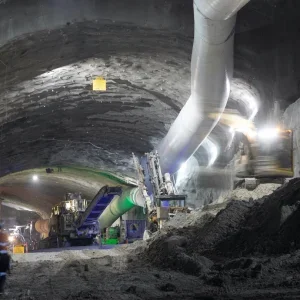
Tunnels under the building – sprayed concrete lining (SCL) with a cast insitu secondary lining – will link to the existing London Underground system. The headhouse is part of the enabling works for the huge new HS2 station at the existing Euston mainline terminal, initially delivering six new platforms, a new concourse and expanded Underground station, and linked for the first time to the nearby Euston Square tube station. A multi-disciplinary team from Mott MacDonald, including individuals from architecture, structures, mechanical, electrical and public health (MEP), tunnels, civils, geotechnical, tunnel ventilation and fire, has been working for contractors CSJV – a joint venture between Costain and Skanska – on the design of the substation, shaft and connecting tunnels.
A Model for The Future
The main shaft is a piled box 20.5m deep and the 6m-diameter tunnels are less than 100m long. A construction shaft will consist of segments in the top portion and a shotcreted lower part as excavation advances, and it will have a cast in-situ secondary lining.
The scale of the project may not be grand, but, with extensive diversion and demolition work going on in the area, it is a complex one, requiring close collaboration between disciplines, contractors, clients and stakeholders, including Transport for London (TfL) and the local community.
Digital delivery has driven our process, with parametric modelling used for the shaft geometry and tunnel, producing better outcomes and more efficient designs for the client. A 3D, engineer-owned model was generated using a series of preprogrammed rules, enabling any change to be automatically applied throughout the model. The corresponding efficiency gains enabled the designers to follow a ‘rapid engineering’ approach by testing different configurations for the conceptual designs within the programme and budget constraints of a fast-paced design and build project.
The model considerably improved communication and coordination, guaranteed consistency with the engineers’ analysis, and produced significant efficiency savings.
Multiple tunnel design options were developed concurrently for the client to review, while parametric design reduced CAD effort by about 30%; it also supported more effective and reliable communication between modelling and engineering teams. In addition, the higher quality of our modelling outputs resulted in fewer errors, less re-work and ensured timely delivery to programme.
To aid management control and ensure the project delivery remained on track, Power BI, Microsoft’s data visualisation tool, was linked to data sources including timesheets, budgets, deliverables, schedules and forecasts, with all the information made available through live dashboards. A project app was developed to efficiently mobilise more than 100 members of staff over the duration of the project. The app captured training needs and competencies to provide a full understanding of the team makeup.
Mott MacDonald’s own in-house software was used to provide the project team with intuitive access to the model, and we worked with CSJV and our partners Bentley Systems and i3P to develop a SafetiBase-compliant solution to collect and manage hazards. This represents the first project to connect CDM hazard registers to the 3D BIM model using the iModel hub.
Under Pressure
The tunnel and the connections to the existing TfL assets are partially situated below the future excavation for HS2’s Euston Station basement, effectively creating two sections – one inside and one outside the station basement box. The planned excavation for the station box reaches a depth of about 13m, leaving just 1m of cover above the tunnel crown. There will be a reloading by the station base slab, plus a planned over-site development (OSD) of approximately 18 stories.
Despite the raft foundations for the planned future works at the station, significant stress changes from the unloading and reloading cycle , and from heave effects, had to be accommodated in the design. Substantial differential deformation – exceeding 20mm over more than 2m at the excavation box boundary – also had to be addressed.
The design of the tunnel must accommodate these load changes and not require any post-construction intervention. At the same time, there must be no disruption to London Underground services.
Key design challenges:
a) Conceptual flexibility was required to allow for changes in the loading, unloading and reloading process, and deformation scenarios due to the evolving design of the HS2 Euston Station base slab.
b) The need to accommodate substantial strain changes from unloading and reloading.
On The Move
Load changes and planned incremental deformations acting on the tunnel are both significant and likely to change during the evolution of the sprayed concrete lining (SCL) tunnel design. This creates uncertainty and led to the selection of a double-shell approach, combined with full movement joints between the approximately 10m-long tunnel blocks, and specific large deformation movement joints at critical locations, such as the boundaries between assets, and at the station basement boundary.
Design of the waterproofing system was crucial, specifically the movement joints. These consist of an external PVC water-bar welded to the PVC sheet membrane, an internal water bar with central pressure relief bulb, and re-injectable grout tubes fixed to the flanges of the internal water bar.
This design can safely accommodate lateral as well as vertical movement in the expected range of 20mm and has been developed to comply with TfL watertightness criteria.
The tunnel is separated – roughly along the tunnel centreline – into a ventilation section and a cable section (see Figure 1). The separation is provided by an in-situ cast concrete wall. To prevent the wall acting as a stiff prop to the tunnel centre, it terminates 20mm below the tunnel crown, with the resulting gap being filled with a fire-retardant material.
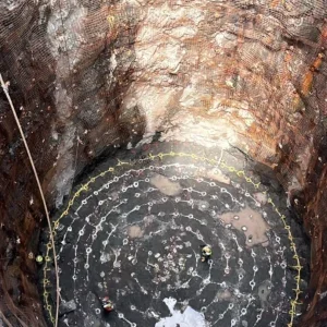
The planned tunnels connect into a disused TfL stair shaft and adit, both of which were originally part of the Northern Line’s Euston Station tunnel complex and provided an entrance on Drummond Street and Melton Street.
A condition survey of the shaft lining was complicated by the presence of tile cladding, but where investigations could be carried out, they discovered some corrosion in the cast-iron shaft lining.
To further improve waterproofing, the existing liner will be modified to provide a cast in-situ reinforced concrete liner. This alteration will also allow fire barrier elements to be installed as necessary. Wherever possible, the re-use of existing infrastructure is a core aim of the project’s sustainability approach.
Early engagement with the supply chain was key due to the complex nature and specific nuances of the project. CSJV’s contractor Joseph Gallagher provided input throughout the detailed design stage. Specialty chemical company SIKA and civil engineers OTB were also actively involved. This collaboration between the consultant and constructors enabled the development of an integrated design that will provide surety for construction. Working closely together also helped to overcome some of the challenges associated with the connections into the existing assets.
Sean Roche, CSJV Civil Design Manager, explained: “Integrating design teams and engaging early with suppliers enabled us to deliver robust solutions to the unique challenges at the site and produce a design that is both buildable and meets all the contractor’s requirements and preferences.”
On The Inside
The primary tunnel lining will be a 200mm-thick fibre-reinforced SCL, with local strengthening of an extra 200mm around break outs. The load changes resulting from the unloading and reloading effects require substantial steel reinforcement for the permanent works. As a result, we decided to use a cast in-situ secondary lining of up to 475mm thick.
Due to the expected substantial movement of the primary and secondary liner post construction, a bonded, sprayed membrane to achieve a composite lining effect was not considered. The shells will instead be separated by a conventional sheet membrane.
Mott MacDonald has extensive experience of SCL, most recently as SCL consultant on London’s huge Crossrail project, where it developed special concrete mixes for the platform tunnels and connecting passages in stations. However, due to the relatively small scale of the HS2 enabling works, the designers, in close collaboration with the contractor, selected available pre-approved sprayed-concrete mixes. They also adopted standard BS 8500-designated concrete mixes for the in-situ concrete, aiming to significantly simplify and accelerate the procurement and construction process.
Geology
As expected, the local geology in this part of the capital is London Clay overlying cohesive Lambeth Group strata. The ground investigation carried out by the HS2 station designer identified the presence of local, semi-permeable strata influencing heave, and highlighted the risk of encountering water-filled sand lenses during the tunnel excavation. Consequently, about 35m2 tunnel face was split approximately 2:1 into heading and invert, with systematic probing included in the construction specifications.
Reinforcement of the secondary lining is driven almost exclusively by the unloading/reloading load cases, particularly from OSD loads, and will consist of installing 32mm steel bars.
Applying Lessons Learned
Mott MacDonald has worked on most major tunnelling schemes in London, including shafts and tunnels in equally congested areas and with similarly complicated geometries. This experience and learning was applied to the HS2 enabling works project, looking particularly to improve health and safety and constructability in relation to the tunnelling works.
As lead designer across the project, Mott MacDonald set out to establish an integrated multi-disciplinary approach from the outset, ensuring the design was developed with all systems and functions in mind. The tunnelling and civil works alone will not deliver the needs of the project, and success will only be achieved when all of these come together through commissioning, handover and operation. To support this, the team chose a fully integrated and digital approach to design delivery, with the aim of supporting the client’s critical programme for construction.
Significant effort went into capturing client requirements, engaging stakeholders and receiving assurance for the scheme through the use of the integrated BIM model and rigorous progressive design reviews in line with HS2 procedures.
Operations and maintenance reviews were a key aspect of this.
Early engagement and close collaboration with the contractors, means we are confident the HS2 design works from both an engineering and a construction perspective. The digital tools Mott MacDonald implemented across the project have provided the client with consistency and efficiency.
The detailed tunnel design is complete, and it has now been CAT3 checked. Final client approval is expected later this year, with construction beginning by the end of 2020. Residents of Stephenson Way, a small street behind Euston Road, and rail passengers will get their first sight of the cube and its tiled facade in 2024, starting the transformation of the HS2 terminus area at Euston.


