


Christopher Hewett, Sub Agent (HS2’s Greenpark Way Vent Shafts) with Skanska-Costain- Strabag (SCS) Joint Venture, was voted winner of the 2024 Competition with a paper entitled ‘Construction of Large Diameter Shafts Within Challenging Ground Conditions’. It is published here with the author’s permission
Greenpark Way Ventilation Shaft (GWVS) project is part of the wider High Speed 2 (HS2) Northolt Tunnels, Lot S2, awarded to the Skanska-Costain-Strabag (SCS) Joint Venture.
The Northolt tunnels are composed of twin bore segmentally-lined running tunnels extending approximately 13.5km-long running between Victoria Road Crossover Box and West Ruislip Portal.
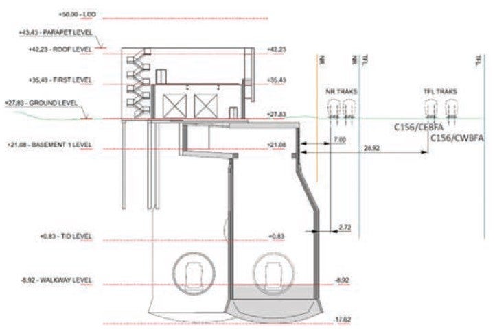
GWVS is formed of a circular Main Shaft of 20m i.d. encompassing the up-line tunnel as well as a circular Satellite Shaft that is 15m at surface level, encompassing the down-line. The Satellite Shaft enlarges to 19.45m at depth, belling out due to surface constraints being within close proximity to Network Rail (NR) assets. Both these shafts are to be constructed to a depth of 45m. The design includes a maintenance adit together with a cross passage connection of the Main Shaft onto the down-line, capped with a headhouse on the surface to house the ventilation fans.
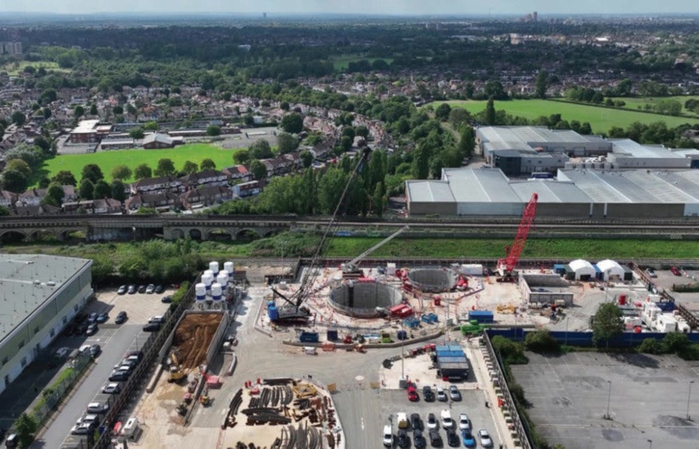
The shafts are being constructed within the Greenford area adjacent to existing third-party assets, notably a Royal Mail sorting office, NR Up/Down Wycombe lines, and and part of the Central Line of Transport for London’s (TFL) underground tube network. The proximity of the NR running lines, situated less than 3m from the site and making them the closet third party asset, has played a pivotal role in the ‘bell out’ shape of the Satellite Shaft.
DESIGN
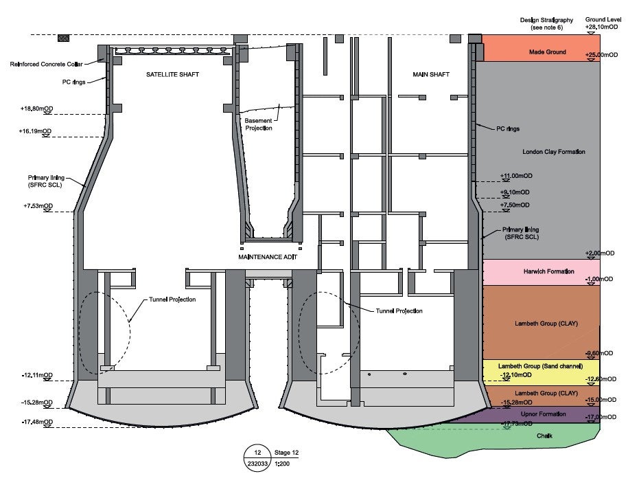
Both shafts are constructed using similar construction methods. Firstly, a primary lining is constructed to support the shaft during the excavation phase. The Main Shaft is constructed using precast concrete rings underpinned for the top 16m of the shaft, before continuing with sprayed concrete lining (SCL) techniques to support the remaining depth. Similarly, the Satellite Shaft also is made up of 8m precast concrete rings and SCL below this to depth. These two techniques have been selected to optimise carbon reduction and efficiency of utilising off-site construction for the precast segments whilst still providing the necessary flexibility of enlarging the shaft diameters at depth for the tunnel opening and receptions.
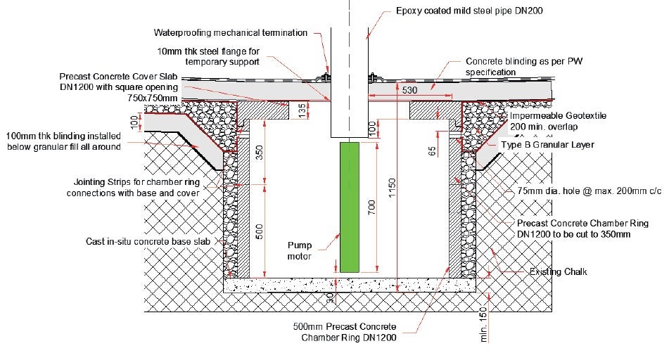
Section chamber for collecting PRW water. Approx 4 l/s
Following completion of the primary lining, an under reamed shaped base slab is to be constructed to mobilise the surrounding soil and balance against uplift forces before a reinforced concrete secondary lining is installed to withstand the full hydrostatic pressure. Implementing the secondary lining in full is a key parameter to stabilise the shaft and enable the full demobilisation of shaft groundwater management schemes.
Greenpark Way will also be the extraction point of the four Tunnel Boring Machines (TBMs) constructing the Northolt Tunnels. To enable reception of the TBMs, both the Main and Satellite shafts need to be constructed with sufficient secondary lining in place to withstand surcharge loading for the TBM extraction lifts. The construction programme is therefore driven by the tunnelling activities.
MY ROLE
I am currently the Sub Agent at Greenpark Way and started on the project in 2020, with the key focus of undertaking the site mobilisation works. I then moved into the delivery management of the shaft excavations and associated groundwater management, which is still being undertaken as of early 2024 and continuing to Q4 of 2024 for completion of shaft secondary lining and in preparation for the reception of the first TBM.
GROUND CONDITIONS
Geology
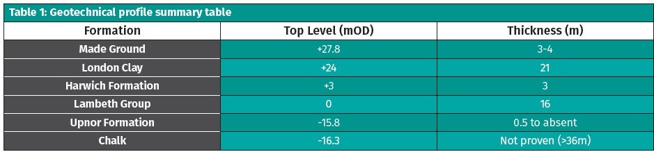
The location of the shafts is situated mostly on made ground, which overlies London Clay (LC), Harwich Formation (HF), Lambeth Group (LG), Upnor Formation (UF), and the Seaford Chalk of the White Chalk Subgroup. The Harwich Formation features sandy silty clay with lenses of gravelly clayey fine sand with the Lambeth Group also featuring lenses of sand. The Upnor Formation sits above the chalk and has been found to feature slightly gravelly sandy clay regions. The chalk itself was found to be heavily fissured and is the level at which the toe of the shaft is founded on.
Hydrogeology
Some of the formations in which the shafts reside are water bearing confined by the overlying London Clay. The lower aquifer of the chalk is a productive aquifer with a piezometric head measured between +17mOD and +20mOD (existing ground level (egl) is at +28.0mOD).
Intermediate aquifers can then be found within the Lambeth Group sand channels and Harwich Formation.
The Lambeth Group piezometric is 1m-3m above the chalk’s head. The Harwich Formation piezometric head sits at +25mOD, only 3m below existing ground level.
A 3-day constant rate pumping test of 5 l/s in 2019 and 25 l/s in 2020 was undertaken to determine the transmissivity of the chalk. The latter of the tests found transmissivity to be in the region of 730 m2/day to 1780m2/day with permeability (assuming 50m aquifer thickness) between 1.7×10⁻⁴ m/s and 4.1×10⁻⁴ m/s. It was also found that a 25 l/s pumping rate produced a drawdown of 2.6m, falling far short of the 46m drawdown required to ensure basal stability of the shaft during construction.
The pumping test also suggested no significant response from the Harwich Formation and Lambeth Group, and so therefore was not likely to respond to chalk depressurisation alone due to low vertical flow. Groundwater management of both the lower aquifer and intermediate aquifers was therefore required to enable the safe construction of the shafts.
Ground Movement Monitoring
Instrumentation and monitoring have been installed on the surrounding areas and third-party assets to monitor for any ground movements that may be attributed to the site activities, including excavation and groundwater management works. In particular, monitoring of movement on the Network Rail assets was undertaken due to its proximity to the Satellite Shaft and site boundary, as previously mentioned.
CONSTRUCTION REQUIREMENTS
To construct both shafts at Greenpark Way, four design conditions in relation to the geology and hydrogeology needed to be achieved. These are as follows:
- Water bearing strata need to be depressurised to prevent any geotechnical instability.
- The excavation face needs to remain sufficiently dry for the SCL to adhere to it.
- Continued depressurisation of the Harwich Formation and Lambeth Group sands whilst the SCL cures and achieves 28-day strength.
- Continued depressurisation of the chalk until completion of secondary lining to maintain basal stability and prevent base heave.
Following initial pumping tests and ground investigations, it was evident that one solution alone would not be sufficient with estimate pumping volumes being in excess of 110 l/s. As such, to meet the construction requirements two approaches were pursued in the groundwater management design combining both ground treatment and depressurisation.
GROUND TREATMENT
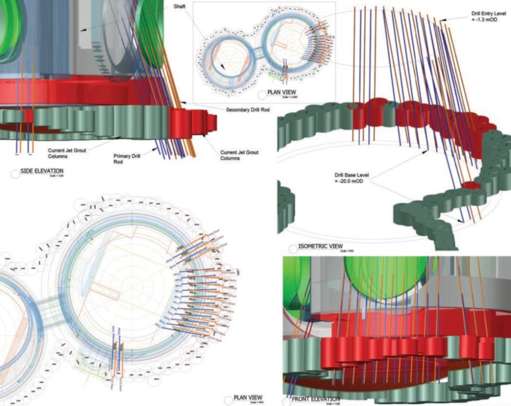
Ground treatment through grouting within the Chalk and Upnor Formation would be necessary to reduce the overall permeability and transmissivity of these formations. Two methods were used:
- Fissure grouting within the Chalk
- Jet grouting within the Upnor Formation.
These techniques were performed around the perimeter of the shaft every 1.6m to create a curtain of grout that would significantly reduce the permeability and therefore requirements of dewatering. For the Satellite Shaft along the site’s southern boundary, the boreholes/columns are installed at an incline due to the proximity to the Network Rail running lines and the ‘bell out’ geometry of the shaft. A performance criterion was produced for the grouting works to reduce the permeability to less than 5 x 10⁻⁷ m/s.
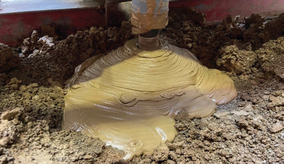
Fissure Grouting
The Chalk is heavily fissured within the shaft area, as found within the ground investigations and subsequent pumping tests. The focus of fissure grouting would be to undertake grouting of the fissures, voids, and faults within the chalk to reduce the overall permeability of the chalk. This would in turn then reduce the volume of water required to be abstracted to achieve the target drawdown. Cementitious grout would be injected at pressure into the chalk to reduce transmissivity across the interconnected fissures.
Approximately 200 No. boreholes were drilled to a depth of approximately 74m to undertake the grouting. The bores were drilled at 1.6m c/c and cementitious grout injected at up to 5 bar, with overlap to adjacent holes to provide full treatment coverage of the shaft area.
Jet Grouting
The Upnor Formation shows more granular and sandy lenses within the formation located above the chalk and would be jet grouted at high pressure to form a cut-off to the shaft’s exterior groundwater. This would provide stability and prevent water ingress and material loss when excavating through the formation.
Jet grouting techniques were used, injecting grout at high pressure (up to 400 bar in this case) to lower the stratas permeability.
There were 84 No. boreholes undertaken with this method, going around the circumference of the shafts. The grout columns were again installed at 1.6m c/c with additional columns completed to fill any gaps detected through monitoring and recording of column deviations.
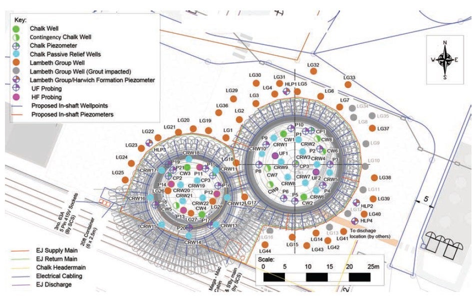
DEWATERING BASE DESIGN
The initial base design for the dewatering system consisted of both a chalk well system and an ejector system. The selection of the system is then derived from the ground investigation, pumping tests and ground water monitoring, after which a design could then be made to select suitable methods based on depth and soil permeability.
Through these initial assumptions, the following describes the base design that was implemented prior to shaft construction commencement. The extent of the dewatering system was based on assumptions of successful performance of the ground treatment works and would only later be confirmed following an initial validatory pumping test on the installed deep wells which would determine if further wells would be required.
Ejector System
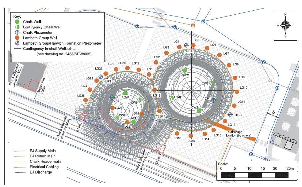
The ejector system specifically targeting the Harwich Formation and Lambeth Group sand channels due to their lower permeability soils and lower flows. The base design was comprised of 28 No. ejector wells around the perimeter of both shafts, forming a figure of 8 arrangement.
Due to the geometry of the Satellite Shaft and the limited surface space between the shaft and site boundary, wells could not be installed along the southern portion and therefore would be reliant on internal wells to supplement. Each of the ejectors were separated by a few metres because of a narrower zone of influence when compared to that of a deep well pumped system. The ejector system instead utilises the Venturi effect, using fast flowing water to generate low pressure to draw water from the targetted region.
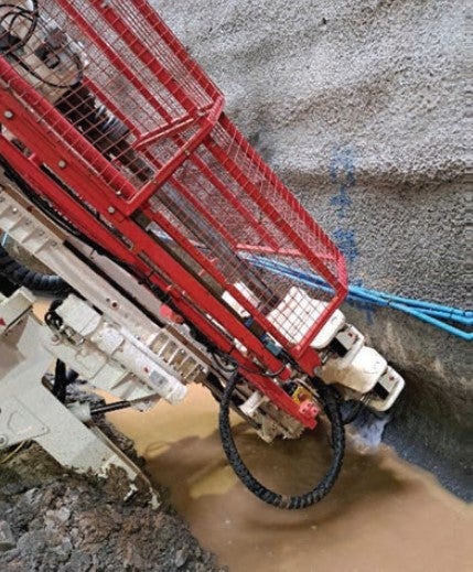
Deep Well System
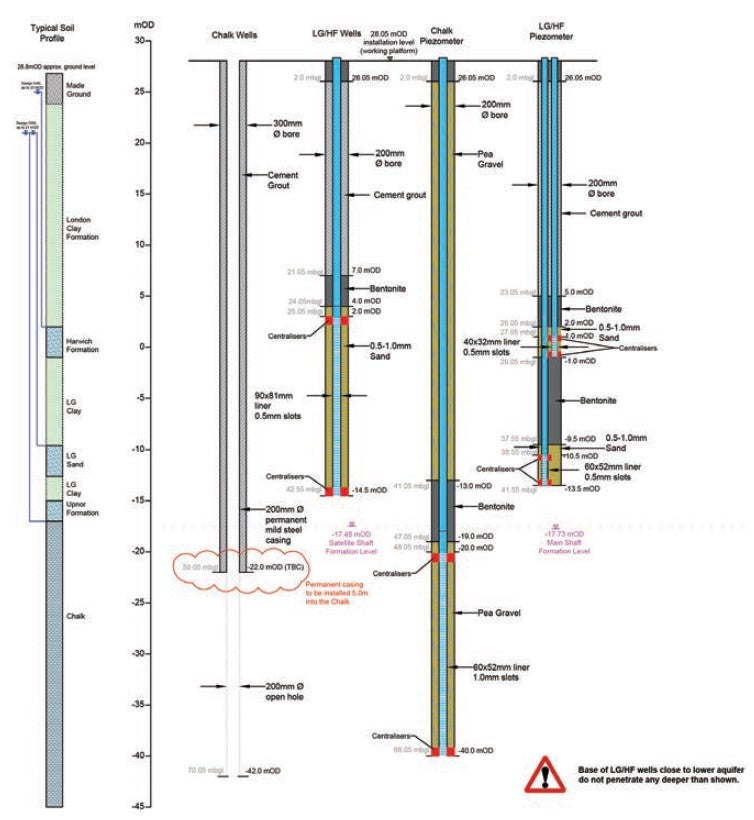
The Chalk was dewatered using a more typical deep well approach consisting of a steel-lined bore drilled approx. 70m deep with a submersible pump lowered to depth. These wells are typically used for soils with high permeability. Given the expected more granular nature of the Upnor Formation, the expectation was that the Chalk would naturally underdrain the Upnor Formation of any residual water following cut-off through the ground treatment. The base design featured 2 No. wells within the footprint of each shaft with a further 2 No. in each as contingency should the validation testing show full depressurisation would not be achieved.
Validation Testing
Once ground treatment and dewatering well system installation were both complete, a subsequent constant rate pumping test was undertaken at 3 l/s within both shafts. This achieved variable results but found the grouting to have very significantly reduced the inflow to the base of each shaft compared to the baseline prior to ground treatment. It would also fall within the parameters to which the dewatering design was undertaken. However, it did indicate the contingency wells would be required to achieve the drawdown and provide sufficient system redundancy. The flow rates now fall within the 20 l/s – 30 l/s range (compared to the estimated 110 l/s previously).
WATER DISCHARGE
All water abstracted from the shafts required a means for discharge to another location. Initial estimates based on the earlier constant rate pumping tests was in the region of 110 l/s to be discharged. This significant flow rate required detailed optioneering of potential discharge routes. Three options were available and assessed as follows:
Option 1: discharge within the Thames Water sewer
- Limited to 8 l/s as per consents.
- Would be suitable for ejector system flows only.
- Therefore, will need to be incorporated alongside option 2 or 3.
Option 2: recharge wells
- Similar in design to the chalk wells installed.
- Installed within the site boundary away from shafts to minimise recharge to the shafts (closest at >40m away).
- Requires consent from the Environmental Agency (EA). Variation to Schedule 33 to be obtained (consent under the High Speed Rail (London – West Midlands) Act 2017, which includes protection and controls for water bodies)
- Variation would only permit the recharge of chalk water to chalk water. Ejector well system cannot be recharged under this agreement without further evidence of water quality due to sites historic industrial use and contaminated land. (This later changed when SCS demonstrated the water quality could be managed to be of suitable quality for recharge.)
- Recharged water to be treated for hydrocarbons by passing through Granular Activated Carbon vessels.
- No clear evidence that the recharge wells would be sufficient in capacity if the design permeability of the grout curtain was not achieved.
- Tests would need to be undertaken on recharge wells and tests on chalk wells (validation testing) to confirm recharge capacity and abstraction volumes.
- 4 No. wells to be installed, including for redundancy.
Option 3: Grand Union Canal
- Grand Union Canal (GUC) is located within close proximity to the northern boundary of the site at approx. 250m away from the shaft positions.
- Requires passing through third party land, including Royal Mail Group (RMG) and Canal and River Trust (CRT) as well as consent from CRT for discharge.
- All water can be discharged to the canal.
Of these alternatives, Option 2 was the most preferable but carried risk due to uncertainty of how receptive the ground would be to recharging with water, as well as the level of performance the ground treatment works would achieve. Due to the third-party interfaces that Option 3 had on top of undertakings and assurance to remain compliant with, it was not possible to simply wait until validation testing was undertaken to decide on a suitable option. It was therefore necessary to progress with Options 2 & 3 during the design development and dewatering system installation phases, with Option 3 being a contingency until validation testing on both the abstraction and recharge wells could be undertaken.
Upon completing the installation of all 4 No. recharge wells, pumping and recharge tests were undertaken by pumping 25 l/s into the wells and monitoring the groundwater levels. What was found was that each of the wells were very receptive to recharging and meant each well could take at least 25 l/s. This paired with the expected abstraction volumes from validation testing, showed that all chalk well water could be abstracted from the shafts and recharged into one recharge well, leaving the remaining three acting as contingency. This was a major success and removed the need for discharging into the GUC. Further on, the ejector system water was proven to be of suitable water quality and was then also recharged alongside the Chalk water.
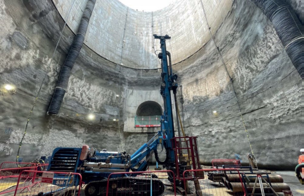
SHAFT EXCAVATIONS
Following the initial completion of dewatering well installation and commissioning as well as the commencement of shaft excavations, it became clear that the drawdown levels required were not being achieved and that further investigation and works would be required.
Target Drawdown
The designer’s groundwater risk assessment provided target drawdown levels required before the shaft could be excavated to depth. Chalk target level is -18.2mOD and -18.0mOD for the Main and Satellite shafts, respectively, both just below the invert of the shaft excavations.
These target requirements were limited to shaft progression, where only partial drawdown is achieved. Further assessment was therefore undertaken to provide additional detail to maximum excavation levels based on the realised drawdowns. A simple uplift calculation utilising EN1997-1 Eurocode 7: Geotechnical Design was undertaken by the designer to assess the interface levels of the Lambeth Group sand channel water pressure acting on the cohesive Lambeth Group clays and the chalk water acting on the Upnor Formation. This assessment provided progressive drawdown targets balancing the need to continue shaft excavations whilst continuing efforts to achieve the required drawdown level to reach full excavation of the shaft.
Unable to Achieve Chalk Drawdown
During the initial operation of the dewatering system following full installation and commissioning, it became apparent that despite the utilisation of the additional contingency wells, the piezometric head and drawdown were not as expected nor as required.
The simple rectification of the issue was to install more wells to relieve the pressure across the footprint of the shaft where there is limited connectivity between the existing wells. As such, a further four wells were added to the Main Shaft to improve drawdown. However, whilst improvements were seen, this did not fully achieve the desired results, falling 9m short of target drawdown level with 5 No. wells operational within the Main shaft (1 No. becoming irreparable following damage).
Installing any further wells becomes another obstruction to avoid within a confined space of a shaft whilst excavating and spraying the SCL. It therefore became a balance of buildability. Installing additional wells would increase the risk of damage to them during excavations, making it impractical to undertake the excavations and sprays. Therefore, it became necessary to assess an alternative solution.
Interestingly, the Satellite Shaft was able to achieve 7m below the target drawdown level with a single well operating at 2 l/s, suggesting significant variation in the level of interconnection between wells and monitoring points, as well as between the Main and Satellite shafts themselves. This was further supported by the significant variation in well yields between 0.1 l/s to 2.2 l/s. It is also possible that whilst fissure grouting has reduced overall permeability, it has restricted connectivity within the shaft meaning that the wells are only depressurising in very localised areas.
A technical discussion between SCS, the dewatering designers and the CAT3 checkers was held to determine an alternative approach that would better suit the needs of completing the shaft excavation whilst still maintaining the required depressurisation of the chalk formation for basal stability. The conclusion was that rather than further pumped wells, a higher quantity of passive relief wells (PRW) could be installed to provide the necessary pressure relief.
Having multiple PRWs across the footprint of the shaft also means that you better relieve any residual pressure rather than the limited area around the few pumped wells which have already been proven to have restricted interconnectivity across the shaft. These would be less intrusive as they would be filled with a pea shingle and could be trimmed with each excavation advance. Furthermore, they would not have any pump or pipework connected creating a further obstruction. Instead, surface water management would need to be undertaken once the wells become artesian.
When the excavation reached the shaft invert, a non-compactable drainage layer was placed on the base dome of the shaft. The drainage layer would allow the water to freely spill from the PRWs and drain to a central chamber in the shaft where a borehole pump could be installed. This arrangement would also allow the water to continue to be pumped out of the shaft following completion of base slab construction, maintaining the required depressurisation.
Unable to Achieve LG Drawdown
Following the initial drawdown of the Lambeth Group sand channels it was evident that the monitoring points were not achieving the desired drawdowns to enable the continuation of excavations, confirmed via additional probing works within the shaft recovering saturated sand samples but proved interface levels align with ground investigations.
Testing was undertaken across the full system to determine well yields, concluding that the northern section of the Main Shaft was seeing higher yields suggesting a greater inflow of water coming from this region. Due to the higher inflows, deep wells could be utilised, similar to those used within the Chalk formation but with a response zone within the sand channels. This would therefore lead to an additional 8 No. surface wells to be installed. This resulted in improved drawdowns but did not yet achieve the targets for excavation. An element of overbleed producing higher monitored results between each well and so would require intervention via another dewatering solution.
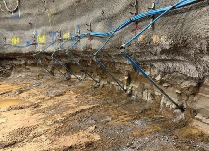
Wellpoint System
A contingency was planned for where the surface wells were not sufficient to achieve what was required. Inshaft wellpoints, installed at 2m increments within the shaft close to the interface level, were used to achieve the remaining drawdown using a vacuum pump system. This system is more suitable for shallower depths of up to 6m, which is why they could not be implemented from the surface.
It was anticipated during the initial base design that this would likely be required in the Satellite Shaft due to the lower number of surface ejectors along the shaft’s southern section. However, given that the ejectors alone did not achieve target drawdown it was necessary to install wellpoints around the perimeter of both shafts. This necessity resulted in the installation of 32 No. and 29 No. wellpoints in the Main and Satellite shafts, respectively, which then achieved the desired result.
Upnor Formation
The jet grouting works were undertaken so as to achieve a key into the chalk formation and above into the Lambeth Group clay, forming a seal within the Upnor Formation. Due to the varying nature of the interface level of the Upnor Formation and adopting conservative modelling of this interface, it could not be determined with full confidence that there was sufficient cut-off within the Upnor to prevent significant inflow of water to the shaft, potentially bringing geotechnical instability, when approaching and excavating through this level.
Monitoring points were therefore installed into the Upnor Formation alongside the installation of the passive relief wells, to provide further understanding of any residual pressure and determine if the permeability performance specification of 5 x 10⁻⁷ m/s had been achieved. The assessed results indicated that full cut-off had not been achieved and therefore further ground treatment would be required. Excavations were paused at the existing level (-1.3mOD) due to the risk of ground instability and increases in the difficulty of undertaking grouting where conditions would become artesian.
Due to potential for ground movement found previously with jet grouting as well as the impracticalities of using large jet grouting equipment from within the shaft at depth, an alternative method was required. This solution would be through permeation grouting, a method utilising a Tube-a- Manchette (TAM) installed within the target region to disperse sodium silicate, a chemical agent that solidifies to form a low permeability compound. Approximately 30 No. TAMs would be installed using a weak cement bentonite sleeve mix and hydro-fractured two days later with additional TAMs installed where deviations occurred. A target of 125 litres of grout would then be injected through each sleeve.
As the shaft excavation level was close to the interface levels of the Lambeth Group and Harwich Formation, surface ejector wells had to remain actively pumping. Efforts were made to minimise grout ingress, including locally turning off wells and passive recovery of the wells following switch off. But along with the grout being injected at pressure there were a number of surface wells that suffered grout ingress. Subsequently, these wells were no longer capable of abstraction. Further replacement wells needed to be installed on the surface to enable sufficient drawdown for the in-shaft wellpoints then to be installed.
Toolbox Measures for Safe Excavation
Following the additional groundwater management works installation alongside additional grouting works, it was clear that despite best efforts there would still be a residual risk of water ingress as the excavations progressed through some of the more granular formations. As such, the ability to be prepared and have in place plans of action to tackle adverse conditions was fundamental to safe progression of works.
In collaboration with the miners and subcontractors as well as the wider SCS engineering team, a toolbox measures plan was devised, describing the various methods that could be utilised by the miners to tackle all potentially expected conditions within the shaft. This included the materials and equipment that needed to be readily available before continuing with the SCL advance.
Where adverse ground or groundwater conditions would prevent safe application of a sealing layer, toolbox excavation and support measures could be implemented. The measures would be discussed in advance within the shift review group (SRG) meeting and instructed prior to commencing the advance where agreed. However, if the conditions of the ground between SRG meetings required further implementation of additional toolbox measures, this may still be undertaken to ensure works can continue safely. The expected measures that may be required would then feature within the Required Excavation Support Sheet (RESS) to provide a one stop location for reference. Some of the measures included: Face depressurisation through installation of bleed pipes; sealing techniques; drainage membrane applications; alternative excavation sequencing, i.e., reduction in advance size; backfilling of opened up area; and, timbering and grouting to stop material loss.
A decision-tree based on planning and implementation was included that would determine the correct course of action. The flow path gave an indicative idea of what measures could be used in what conditions. The tree would therefore provide guidance in the process of decision making by the person in charge, lead miner, shift engineer manager in between shift review groups to enable continuation of works and allow for immediate action upon encountering adverse ground conditions. The shift engineer would then record and document any toolbox measures sued and report back within the next SRG for review.
CONCLUSION
The Greenpark Way Vent Shaft works are large diameter shafts being constructed in challenging ground conditions and therefore demanded a broad range of strong engineering solutions to continue the works. A considerable amount of collaboration from inception to on-site construction has been undertaken particularly between SCS, the specialist subcontractors, designers and checkers.
This project has shown how despite all the testing, monitoring and ground investigations undertaken, geology and hydrogeology can be fickle. The initial base designs compared to today’s design have shown significant design development as works progressed and more of the nature of the ground becomes known. A design, when looking at the dewatering systems alone, started at 32 No. wells and developed into 136 No. wells and approximately 25 No. validatory bores.
As of the writing of this report, the Main Shaft has now been successfully excavated to depth with a further 8m of mining remaining in the Satellite Shaft. Dewatering will continue until the completion of secondary lining, expected to be during Q4 of 2024.
Whilst initial designs did not achieve drawdown targets as originally anticipated, a careful balance of safely continuing construction whilst developing further solutions was struck. Concepts were challenged and alternatives were developed, ensuring that solutions implemented provided both necessary performance whilst continuing to provide reasonable practicability of shaft construction.
Ultimately, the difficult ground conditions have prolonged previous expectations of shaft construction. But there has been a great success in the overcoming of the many blockers and challenges these conditions presented throughout the construction process. This could only have been achieved through clear and cohesive collaborative working between delivery and design.
Q&A – SUMMARY
Following his presentation, Christopher Hewett took questions from the BTS judging panel and the audience.
A question asked on schedule versus actual construction time on sinking the shafts. The answer was that works began in September 2022 and finished recently, prior to the talk, and so the challenges did have a large impact on the construction programme.
Another question wondered – if you were to start again, how proceed? – and the answer pointed to more ground investigation, and ideally having more time for such, early on – and dewatering, as required. Such extra investigation would have helped to more fully appreciate what they would have to excavate through, and ideally have the dewatering system up and running, in full, achieving what was needed, before continuing on. On the project, a balance needed to be struck as part of the larger construction programme (with TBMs on their way), with design iteration proceeding and continuing with the shafts, constructing them safely.
A further question asked about the fundamental method of sinking the shafts – would they use that same method again? The answer was that given the location of the shafts it was as good as they could get, adding that having the shafts in a different location would have helped quite a bit.
A follow-on question then wondered about use of diaphragm walls, and while its merit was acknowledged the site was restricted by proximity of rail assets.
On the iterative development of the solution, there was much collaborative effort with SCS’ engineering team and the dewatering subcontractor. He worked daily at the forefront to get the shafts constructed. Challenges included discussing options, such as on passive relief wells, with so many pumping wells already in the shaft.
The works had extensive ground monitoring in the vicinity with regard to third party adjacent assets. Communication is key – understanding issues involved is the only way to move forward effectively; he said this needs to be the approach to take on these sorts of challenges.
On Toolbox measures, he said there weren’t new solutions but they ensured it worked as a single information system, with details of all methods and materials, given in a decision-tree process, readily available if required.
He was thanked for the presentation and taking questions.


