Historically, The Gotthard Pass has been a major north-south access route through the Alps. The first recorded structure being a wooden bridge built in the 1230s and named the “Devil’s Bridge” by the locals, the Devil gaining his revenge by destroying the bridge in a storm. The first tunnel was opened in 1708 thus forming the first Gotthard Tunnel.
Project Overview
A key objective of the Swiss government has been to remove HGV traffic from the Alps and increase freight capacity as part of the European Freight Network. The European Freight Network requires “flat” rail levels and hence the tunnels currently under construction and those opened in the last decade are much deeper than the older tunnels and are therefore termed “Base” tunnels. Indeed, before construction of the Base tunnels, freight trains from Germany had to be split in two at the Alps as the trains were too heavy to accommodate the gradients.
The Lotschberg Base Tunnel (34.6km long) was opened in 2007 and nine years later the Gotthard Base Tunnel (56.7km long) came into operation. These two routes and the Brenner Base Tunnel, which is currently under construction, are aligned north-south, while the Lyon-Turin route planned for opening in 2030 follows an east-west alignment (Figure 1) The Swiss government is a funder of all these schemes.
Another factor in the development of the scheme is that the current rail tunnels in Switzerland are too small for generic European freight rolling stock. The Swiss Federal Railway utilises specific low-profile rolling stock which operate only within Switzerland thus requiring double handling of freight at the country’s borders. Therefore, in parallel to construction of the new Gotthard Base Tunnel several existing tunnels have been enlarged and upgraded.
There is some competition between Gotthard Base Tunnel and Brenner Base Tunnel as to which tunnel is longest, but Yves believes that the Gotthard Base Tunnel is and will remain the longest rail tunnel in the world even when the Brenner Base Tunnel comes into operation.
The Gotthard Base Tunnel is funded by the Swiss Federal Government following two referenda and the operator is the Swiss Federal Railways. The builder is AlpTransit Gotthard, which includes three contracting teams and two designer teams.
During the scheme’s development a number of tunnel configurations were considered including:
- A Channel Tunnel style arrangement with two single track bores and a central service tunnel providing a dedicated intervention and escape route but given the tunnel’s length this was dismissed.
- Similarly, three single-track bores were considered with two in operation at any one time and the other facilitating intervention/escape but also allowing more flexible maintenance access. This was not progressed on cost grounds, however.
- Two single-track bores with cross passages facilitating escape to the adjacent bore which proved to be the selected configuration.
A consideration of the chosen system was maintenance access as temperatures in the tunnels can reach 37°C, but operatives are not permitted to work in temperatures greater than 28°C. With only a six-hour maintenance window each night and significant distances for the maintenance crews to travel waiting for temperatures to naturally fall was not considered possible and doors were introduced in the tunnels to allow localised cooling of the work areas.
The tunnel diameter is 8m ID allowing an average of 41m2 free area through the tunnels in order to address frictional effects around the train. In general, the spacing between bores was 40m but to address tunnel interaction in certain ground conditions it was locally increased to 70m. The section provides for a waste water drainage system to facilitate a fuel spillage of 40m3 and a separate 600mm diameter drainage pipe, the size determined by predicted inflows and the minimum size to accommodate a person (Figure 2).
The spacing between cross passages is 312.5m, which is less than the 500m defined in the norms and was determined through detailed study of operational scenarios and required escape times. The norms also call for emergency stations where the tunnels exceed 20km in length and therefore two were provided at Sedrun and Faido (Figure 3). These multi-function stations provide fresh air supply and ventilation to the tunnels plus crossover structures.
Preparation and Prequalification
The design life of the tunnels is 100 years including the drainage system If this stops functioning the linings would fail. A special committee of experts defined the testing to meet the design life criteria for linings and waterproofing and this group was involved in verifying the regime during construction too.
Suppliers had to be specifically certified to meet the project criteria and the contractors were limited to using these suppliers. Only two waterproofing suppliers were certified and after intensive testing only a limited number of membranes were accepted for use on the project.
The durability testing of the concrete included tests of over two years in duration and intensive working life testing in the Hagerbach facility. However, in some cases the contractor even elected to over specify the concrete given the logistical challenges of delivering concrete over such great distances.
Another example of the scale of this project is an anecdote from one of the contractors: if one less bolt was required per sleeper supporting the double track construction railway system, this would result in a cost saving of over EUR 1M (USD 1.1M).
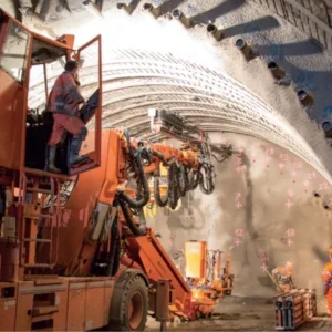
The geology included Aare Massif, Gotthard Massif and Pennine Gneiss zones with intermediate zones of the Tavetsch Massif and Piorat Syncline. The tunnels were primarily excavated by TBMs with a section of drill and blast from 800m deep shafts at Sedrun through the Tavetsch Masif. Additionally, drill and blast was used at Sedrun and Faido Multi-Function Stations.
Challenges during Execution
Piora syncline
There was a contingency allowance in the contract of EUR 25M for ground treatment of this zone. An investigation tunnel was specified at 5.5m in diameter and 5.5 kilometres long. The temperature of the groundwater generally increases with overburden and as the exploratory tunnel overburden increased along the length of the tunnel, the crews realised they had found the zone as exploratory core holes found colder water. Exploratory holes were drilled through a preventer, but during a change in tools and while the preventer was open, 400m3 of loose material came into the tunnel through the hole (Figure 5).
Given the potential for 150 bar water pressure there was concern that TBM tunnelling would not be feasible in this reach and that this length of tunnel would have to be undertaken in advance of TBM passage. 7,000 linear metres of core drilling was undertaken to investigate further, and it was discovered that there was no water at tunnel horizon due to the presence of a gypsum cap above the proposed tunnel crown. This cap blocked the passage of water through the material above in the near vertical syncline. It was concluded that the TBM could traverse this section. During tunnel construction probing was performed from the front of the machine to check there were no cracks connecting the water bearing material above to the tunnel horizon. Tunnelling through the section was uneventful and indeed the rock was smooth and soft, a perfect tunnelling medium.
Tavetsch
Squeezing ground was identified as an issue and therefore the design called for this section to be undertaken off the TBM critical path. To address the anticipated 700mm radial deformation steel profiles rolled to the tunnel diameter with joints that can accommodate slip (based on methods used in the mining industry) were specified in the sprayed concrete primary lining (Figure 6). The section was intended to be excavated full face to give almost immediate ring closure.
Faido multi-function station squeezing ground
Exploratory holes were drilled from the adjacent investigation tunnel and the geology was predicted to be as assumed in the design however at the southern end of one of the main caverns a face collapse was experienced. The tunnel had intercepted a fault zone of around 100m in length comprising weak rock. Radial deformations of up to 1.6m were observed during tunnel construction. The heaviest steel sections that could be rolled to the tunnel diameter were employed but deformed excessively in the conditions encountered.
The designers reviewed alternative layouts for the caverns to mitigate the issues with the fault zone, but it was concluded that there was no benefit in a revised configuration. The designers specified a 600mm thick sprayed concrete primary lining with windows in the lining (Figure 7) to allow for deformation and this was followed up in the subsequent days, once squeezing pressures had reduced, with a thicker sprayed concrete lining. Installation of this thicker second lining was limited to no more than one week after excavation of that section.
Rock bursts
Another issue encountered was rock or “mountain” burst. Rock burst is associated with the excavation surface, but this was deeper-seated and was identified in areas where soft rock was adjacent to pillars of competent rock with the load shed from the soft ground to the rock pillars leading to cracking in the rock and shaking of the rock around the excavation. A magnitude of 2.4 on the Richter Scale was observed during one instance and up to 100m2 of rock could fall from the excavation surface in one episode.
As the second TBM passed through these areas the already constructed tunnel was subject to additional dynamic load and the rock bolts were observed to fail. In these circumstances the first tunnel was closed to all traffic/personnel.
TBM squeezing
The Chiera Synform was expected but was encountered 600m further north than predicted and had significantly higher overburden than the design assumed. The squeezing ground deformed the steel arches in the lining excessively and inhibited the 450m-long TBM back-up. This resulted in sections of the back-up being removed or amended.
Additional support, e.g., heavier arches were considered but this was thought to slow the support installation, thus inducing higher squeezing pressures, hence no value was provided. Another issue in this zone was additional deformations induced in the previously constructed adjacent bore during TBM passage which required repair of the first tunnel.
TBM face collapse
In one location there was a face collapse in the TBM with a cavity formed above the cutterhead. The rock in this area had significant variation in ground behaviour between the two bores. Although there was a separation of only 40m, the first TBM encountered no face stability issues but the second experienced a face collapse.
Despite efforts by the contractor to treat the ground ahead of the TBM and adoption of forepoling the TBM could not be advanced. Subsequently a niche was created in the adjacent bore to allow grouting ahead of the TBM and a temporary tunnel progressed to meet the TBM cutterhead. After a 132-day delay, 3,500m linear length of drill holes, 120m3 of cementious grout and 100m3 of gel-injection to protect the cutterhead, the TBM restarted.
Lining
The final TBM breakthrough occurred in March 2011. An average advance rate of 10m/day over the 85 linear kilometres of TBM drives was achieved which matched the predictions at the time of design.
Cross passage construction followed approximately 2km behind the TBM. The final lining was installed by a travelling machine termed ‘the worm’. The 700m long train included double construction railway tracks to allow trains to supply the TBM ahead. The waterproofing was also installed within the worm and the membrane included velcro fixings ahead of final welding. Curing and repairs plus enlargement of areas subject to squeezing were also undertaken within the worm.
Surface Works
The tunnel opened for service in June 2016 and tours of the tunnels are possible including a viewing window in the side of one of the tunnels where the public can view trains speeding through the tunnel system. A number of landmark surface headhouse structures have been provided and although attracting some criticism for their cost are considered appropriate as they are the only evidence of the EUR 8bn (USD 8.91bn) underground infrastructure below.
Arisings from the tunnel’s construction have been used for concrete production for the project, reinstatement of islands in local lakes and refilling of quarries.
Lessons Learned
The key lessons learned include:
- The TBM design needs to consider allowing sprayed concrete support to be installed closer to the face to provide flexibility in squeezing ground.
- The relatively simple gripper TBM was the right decision and a shield with PCC lining would have been problematic in the squeezing ground conditions encountered.
- Probing ahead of the TBM was useful as it helped mitigate some potential delays and the drilling was generally undertaken during maintenance shifts so had no production impact.
- It was not enough to have competent designers and contractors but also a specialist client is needed who understands the risks, geology and technologies involved.
- Intervention plans are required to deal with a number of what ifs for example, some equipment needed for particular mitigations had a six-month lead-in time and the client decided to purchase such plant to make it immediately available if it were needed.
Questions from the floor
Anonymous: Could the Base Tunnels have been built 50 years ago?
Answer: Yes, in theory. A representative did visit a number of mines around the world to research techniques and technology, but this was largely available 50 years ago. Probably the TBM advance rates are greater and given the tunnel length the likely duration might have made it infeasible. A good example of this is a potential tunnel from Gibraltar to Africa which given the difficult ground conditions will only be possible with slow advance rates making the tunnelling duration so long it will not suit the political cycle. The geology has created significant challenges and at the Fabio multi-function station the encountered conditions have meant a re-examination of theory of how the Alps were formed. The structures here cost EUR 500M more than anticipated so given enough time and money it could have been achieved 50 years ago.
Rosa Diez, Mott MacDonald: The speaker mentioned that only 50% of the waterproofing products tested actually passed. This seems very low?
Answer: The testing was undertaken before the current requirements as defined in the guidance such as Austrian norms and therefore the products were not all up to the needs of the project at that time.
Sarah Smelling, HSE: What was the biggest challenge in terms of Health & Safety on the project?
Answer: In relation to construction the biggest risk was fire given the tunnel length. Rescue chambers were provided within the tunnel system and on the TBM. In fact this project was undertaken at the same time as the A86 tunnel in Paris where the workers on the TBM had to remain in the rescue chamber until firefighters could safely access the chamber. There were a lot of firefighter exercises and where the local firefighters did not have specific tunnel experience special firefighting teams were formed by the project. There were eight fatalities on the project, one of which occurred due to falling rock and the remainder happening during transportation and installation activities.
Donald Lamont, ex Head of the Channel Tunnel Safety Authority: How does the operator evacuate trains if there is an emergency between the multi-function stations and how are the passengers controlled within the train tunnels?
Answer: Control is provided by the train driver and there are also trained staff on the train. The passengers are told to move to the nearest cross passage and then to the adjacent tunnel from where a train will pick them up. The doors on the 150 cross passages are designed to open under the high pressures during ventilation operation. The ventilation system has been designed such that there is enough time for all passengers to reach the point of safety, i.e., the adjacent bore.
Mohamad Fahed, Mott MacDonald: What site investigation was undertaken?
Answer: There are some existing tunnels which provided information. As noted in the presentation some investigation tunnels and exploratory drillings were undertaken. Discrete boreholes would not have been able to locate the faults detailed in the presentation and as one of the site geologists said “ I will predict the geology once the tunnel is excavated.” In one section the first TBM passed through competent rock and over the same length the adjacent bore encountered a fault in the crown of the tunnel over a considerable length. Site investigation would not have picked up this feature.
Luis Pinilios Lorenzana, Mott MacDonald: Luis queried the approach to the tunnel drainage design.
Answer: The global water pressures are very high but local to the tunnel the pressures are manageable for the lining. In fact, in the squeezing ground any cracks/discontinuities in the rock tend to close up and therefore the water inflows reduce. Significant modelling of the hydrogeology was undertaken to see if there would be detrimental effects due to changes in the groundwater caused by tunnelling on third party structures. Most notably a dam was studied to assess how much settlement would be induced and it was concluded that the movement would only be a few millimetres, which was within acceptable limits.
David Harold, LBA: Could you give more details on the fire/intervention strategy during operation?
Answer: Firefighting trains are distributed at various locations along the tunnel alignment but the anticipated time for fire crews to reach a fire is at least 30 minutes and therefore the evacuation in the tunnel is managed without the fire crew in attendance. Fire loads assessed were between 20MW to 150MW and the worst case is a truck train as the fire load from the freight is high, but the truck drivers are also present on the train.
Gerry Conway, independent consultant: If the rock burst was having a significant impact on the adjacent bore did you consider increasing the separation between tunnels?
Answer: Yes, but given the constraints of the rail alignment it would take 1.5 to 2km to provide enough horizontal separation and as the rock burst areas were generally not predictable and very local it was not possible to adjust on site. The only exception is at Sedrun where the designer anticipated that there would be a large interaction between the two tunnels and decided to increase the separation to 70m.