David Maddison, Associate Director of Tunnelling with Jacobs, and working on Hinkley Point C project as the Offshore Connections Design Manager for the Marine Works, was a runner-up in the 2024 Competition with a paper entitled ‘The Design and Construction of Complex Offshore Structures: the HPC Tunnel to Shaft Connections’. It is published here with the author’s permission
INTRODUCTION
Hinkley Point C (HPC) is a critical programme that will help the UK to meet the United Nations Sustainable Development Goals1 and its commitments to reaching Net Zero carbon emissions.2 HPC has the UK’s first nuclear safety qualified tunnels, shafts and heads which requires stringent approvals, documentation, and quality standards to be complied with throughout the design and construction process.
To construct the tunnel to shaft connections (TSC), the Marine Works (MW) project has used recent advances in technology in combination with established tunnelling construction practices to deliver works in an overall safer and more cost-efficient manner whilst maintaining the standards required within the nuclear industry.
This paper uses the TSC as a detailed example where interdisciplinary collaboration has been effectively used on a UK major infrastructure tunnelling project. While the underground works continue, the paper shares recommendations to the industry for adopting best practices and lessons learnt.
PERSONAL INVOLVEMENT AT HPC
I have been involved in the MW project of the HPC3 programme since 2014 and almost full-time since graduating, in 2015. Working with senior colleagues, I initially undertook three years of detailed design to nuclear assurance standards for multiple onshore tunnel and shaft structures. I subsequently transitioned to a primarily site-based role.
Since mid-2018 I have been working alongside the Balfour Beatty (BB) engineering and site teams to support the tunnels and shafts permanent works (PW) design approvals by the ultimate client, New Nuclear Build GenCo (NNB) and construction of these structures. To achieve this, I fostered a collaborative approach working between Jacobs, BB and NNB which has continued for the TSC element of works.
From 2018 to early 2023 my role was primarily to lead the design coordination, including: support for the manufacture of the 37,484 nuclear-qualified precast concrete segments; the construction of three main tunnels; and, the construction of nine other onshore tunnels, galleries and shafts of varying geometries and functional requirements. I became a Chartered Engineer with the ICE in 2019.
Since the start of 2023, I have been leading a large Jacobs team to implement the accepted design of the offshore TSC. This has involved considering, implementing, and sharing lessons learnt from previous and ongoing work, managing design changes and facilitating collaboration between the Jacobs (site and office-based) and BB teams, BeMo Tunnelling (independent TSC supervisors) and other interfacing teams, including NNB.
TSC OVERVIEW & CONSTRAINTS
HPC is a new build nuclear power station under construction in Somerset, UK. It is the first nuclear power station to be constructed in the UK since Sizewell B opened in 1995. Due to the recent closure of the adjacent Hinkley Point B and other aging nuclear facilities, the timely completion of HPC, including the MW tunnels and shafts, is critical to ensuring future energy demands of the UK can be met, and in a sustainable manner.
As these are the first nuclear-classified tunnels and shafts to be designed and constructed in the UK, I have helped BB to develop the documentation processes required to meet NNB quality assurance requirements. Due to my extensive involvement on the project, to help share knowledge I have participated in multiple lessons learnt workshops covering all aspects of the project. This information sharing will help to improve the buildability of future nuclear projects such as Sizewell C, and the wider industry.
The layout of the MW includes: There are three segmental tunnels (2 No. 6m-dia. Intake Tunnels and a 7m-dia. Outfall Tunnel) and at the ends are six TSC (two per tunnel) at depths of up to 27m below the seabed, and approx. 1.8km-3.5km offshore from the main HPC site (see Figure 1). Located within the Bristol Channel, the TSC are in an environment with an extreme tidal range (up to 17m).
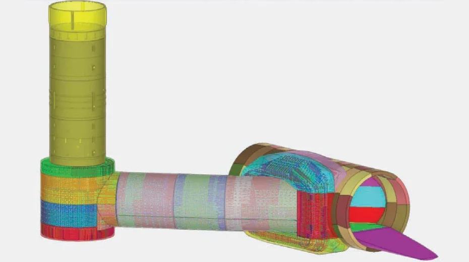
The TSC is a critical element of the MW cooling water system (see Figure 2). They act to connect the segmental tunnels with the heads that have been prefabricated and previously placed on the seabed.4 During operation these structures will allow the transfer of both intake and outfall water to and from the power station. There are six similar TSC, approx. 20m. deep and with 4.2m final internal diameter.
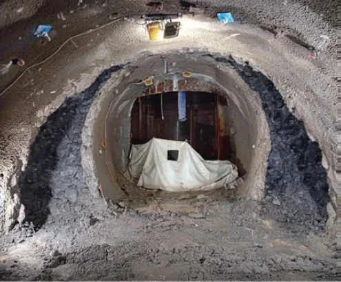
Within the TSC, several temporary works (TW) techniques are used. Vertical shafts are located offline from the main segmental tunnels (see Figure 2). The shafts are formed using prefabricated external steel liners, taken offshore and lowered to tunnel level, each into a drilled socket to be grouted into place. Using an isolation cap, the working environment is sealed from the Bristol Channel and enables mining out from the segmental tunnels, then to form horizontal adits and 90° ‘elbows’, employing rock bolting and sprayed concrete lining (SCL) support techniques.
The PW are formed using cast in-situ reinforced concrete (RC) designed for a working life of at least 85 years.
After considerable optioneering, an offline arrangement for the vertical shaft and adit in relation to the main segmental tunnels was selected. The choice was primarily to minimise the identified risks from seawater inundation, and also constructability for an inline connection and to provide an optimised hydraulic arrangement. To achieve the hydraulic requirements and minimise system head loss, the geometry of the TSC connection was optimised for the final PW arrangement connection to the segmental tunnels.
TSC TEMPORARY WORKS
To allow the final PW structures to be constructed it is necessary to first create a temporary space proofed conduit within the bedrock that must remain stable and secure until the PW have been built. The minimum planned working life of the TSC TW is two years (note: it will be left in-situ behind the PW). An overview of the TW procedures and techniques used is given in this section.
Other elements of TW, such as the primary/secondary bulkheads and lifting arrangements, are not covered by this paper due to being designed by others.
TSC design & construction approval
Owing to the extremely complicated and innovative nature and the nuclear safety functional requirements of the TSC, this necessitated the highest level of design verification to be aligned and integrated with the planned construction methodologies. The overall design process also included an Expert Panel review of the proposals.
The Expert Panel of industry leading independent technical experts scrutinised the planned works and designs. They provided assurance that the design and construction plan was robust and adequately mitigated the project risks associated with inundation of the works by the Bristol Channel, thus supporting NNB in clearing the critical hold point to start construction of the TSC.
The TW design was also CAT III checked by an independent designer. It was therefore important that construction changes were managed and not enacted without prior consideration of the potential impact, including category of change, and that unplanned deviations from the accepted design do not occur in the field.
Communication & collaboration
Once construction works began, to facilitate enhanced collaboration between the Jacobs back office and sitebased design team, and the BB site-based construction team, I developed a detailed but flexible procedure defining responsibilities of the team members and the lines of communication to review and enact changes. This was effective and gradually adjusted to suit the needs of the project at its different stages.
Throughout the TW adit construction, I provided the link between site and back office teams and actively participated in the daily review meetings (DRMs) as the Jacobs design manager. With participation from multiple parties and being led by an independent organisation, BeMo Tunnelling, the meetings enable group consensus to be reached following review of monitoring and geotechnical data to identify possible movement trends and any requirement for toolbox measures. To ensure works are undertaken in a safe and effective manner in line with the design requirements, the DRMs thoroughly review completed and planned works ahead of the next phases of activity. To control work in the field, the DRMs develop agreed Required Excavation Support Sheets (RESS) documents from the design.
Probing & grouting
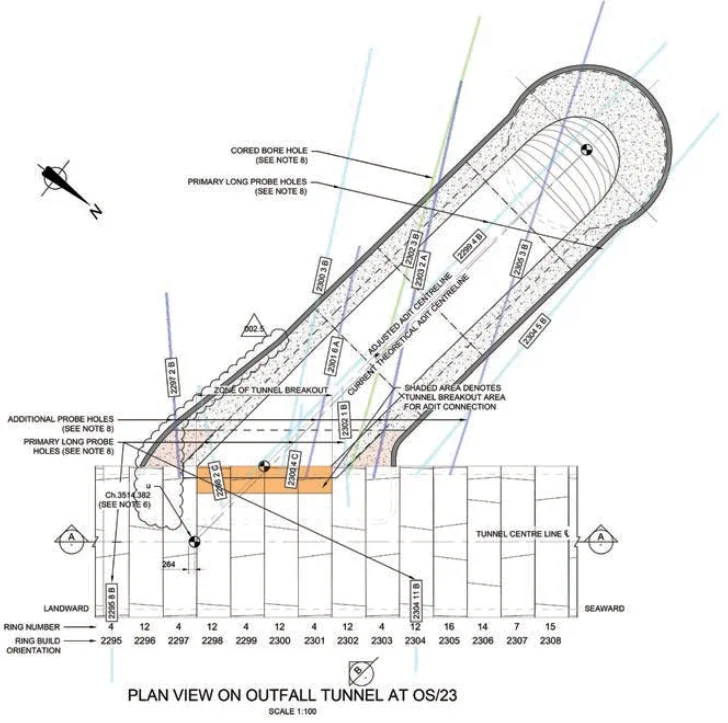
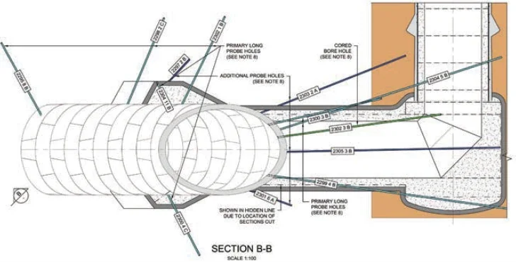
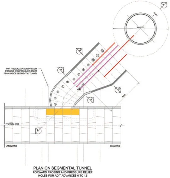
At each TSC location, the original ground investigation consisted of a single shaft borehole. To verify the ground conditions and associated design, a further
investigation was undertaken using core holes, prior to mining breakout from the segmental main tunnels and commencement of main TSC construction work (see Figure 3).
Following breakout from the segmental tunnels and prior to each significant advance of the SCL adits, further forward probing holes were installed to inform the contractor of the likely ground conditions ahead.
To allow the ground conditions to be better understood, throughout the construction of the TSC, the geotechnical information obtained from probing and mapping the tunnel face is logged within a 3D geological model to allow it to be scrutinised and called upon as required in future.
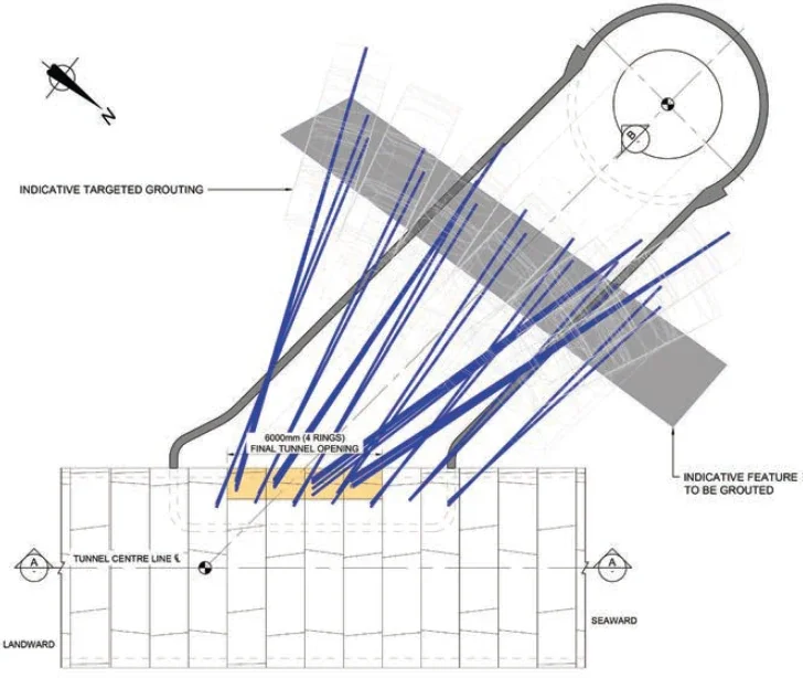
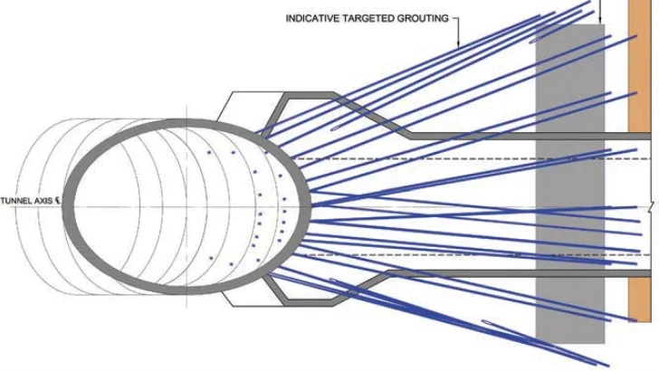
To reduce the severity of likely water ingress to permissible levels during the construction of the TW, a significant campaign of probing and grouting gets undertaken prior to breakout from the segmental tunnels. The extent of grouting required varies by location depending on the ground conditions encountered, and due to the need to balance time and cost against likely reductions in flow without fracturing the ground. Grouting was undertaken using microfine grouts due to the specific hydrogeology of a location. See Figure 4 for an example of a geological feature being grouted.
Hydrology, geology & pressure relief
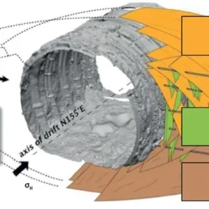
At the location of the TSC, the geological formation is primarily horizontally bedded limestone and mudstone of the Lias Group.5 Due to the presence of discontinuities and fractures and potential pathways linked to the Bristol Channel, significant water pressure could act upon the lining.
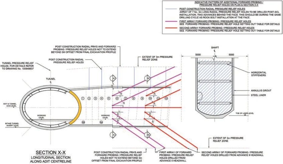
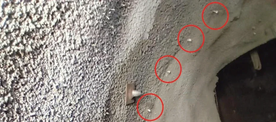
To account for this potential pressure and to optimise the overall TW design of the TSC, arrays of pressure relief holes (PRH) were prescribed to be installed throughout the structures to a depth of 3m beyond the extrados of the SCL (see Figure 5). This means that the SCL is not required to resist the full groundwater pressure that would otherwise act upon it (up to circa 5 bar). Theory of stress increases in horizontally bedded rock6 demonstrates that it can become significant due to water pressure build-up and must therefore be relieved to ensure continued stability. The required length of the PRHs is, however, harder to determine and should be based upon engineering judgment for the specific construction case being considered.
Whilst it can seem counter-intuitive, a PRH that remains dry is still functioning as required in relation to the design requirements. If significant flow occurs within a PRH it would need to be piped and pumped away until the completion of the PW, at which point it can be backfilled for the PW lining is designed to withstand the water pressures.
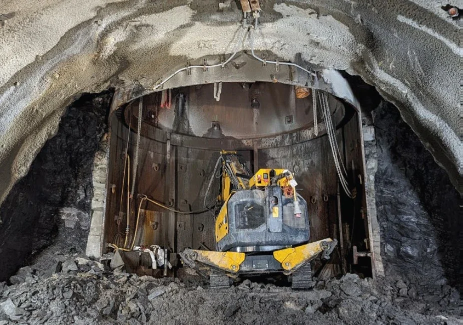
For the correct formation of the PRHs, which must reach a specific target zone, and undertaking rock bolting (see below), the space proofing of plant is critical in relation to required drilling and installation angles.
To resist the uplift of the shaft liner due to buoyancy resulting from the displaced water (see below), additional PRHs are prescribed to be installed below the shaft location.
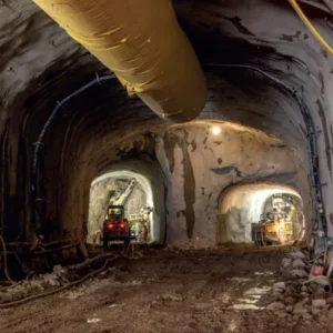
Tunnel excavation & SCL
For each of TSC, approx. 800m3 of rock needs to be excavated, in 50 No. approx. planned advances and enlargements.
As part of each advance, the geology is assessed (see Figure 6) and a Rock Mass Rating (RMR) determined. This is then compared to the design assumptions and used to estimate rock stand-up times.
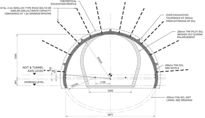
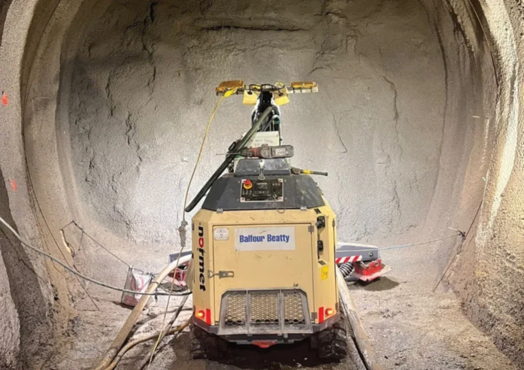
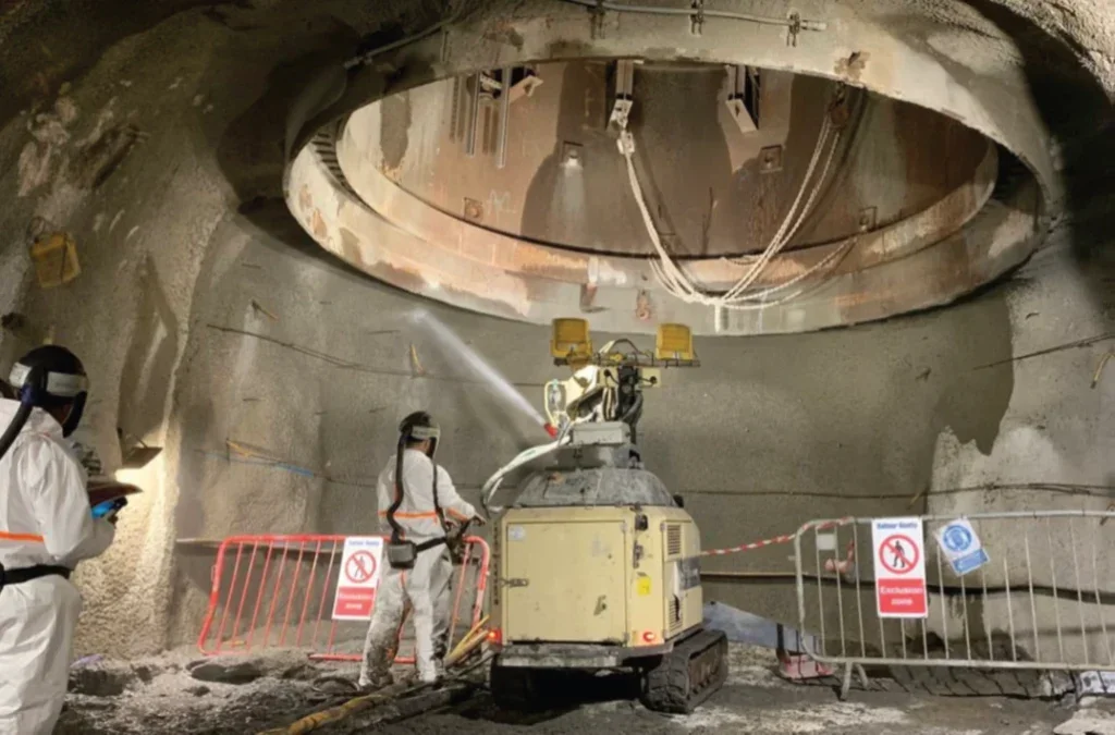
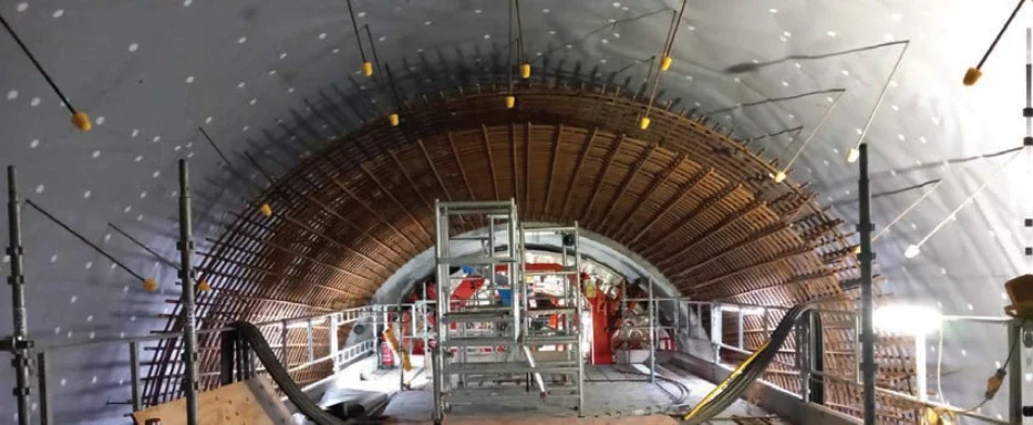
In the TSC, the SCL is applied in two separate passes of 100mm minimum thickness. The primary function of the first layer is to immediately stabilise the exposed ground prior to the installation of rock bolts; the second layer provides the required design thickness. As the TSC SCL does not need to resist the full groundwater pressure, it can be relatively thin at nominally 200mm thickness, which reduces material use and provides a significant carbon saving to the project.
The primary SCL used in the TSC is a pre-blended mix that must be stored distant from the works face, in silos, at the entrance of the segmental tunnels. To maintain mix consistency, it is important to not allow the silos to fully empty as the contents could potentially segregate by particle size within the silo. As an emergency measure, should there be an issue with supply of the primary mix, bagged shotcrete is available at the active works locations.
Onsite meetings between the Jacobs and BB materials teams were facilitated to review the requirements of the mix and to ensure alignment between the teams.
During trialling, consideration was given to the development of summer and winter mixes to allow for more consistent and predictable performance throughout the year. The quantity of water used when batching must also be carefully controlled to ensure early age strength gain is achieved.
Rock bolting
When installed, the staggered arrangement of 2.4m-long rock bolts act to stitch together the horizontally layered bedrock to form an effective rock arch, which redistributes the stresses induced by the excavation formation.
As shown in Figure 6, the smaller pilot tunnels used in the TSC were designed to not require rock bolts until enlarged, later in the excavation process. The pilot tunnels did not require planned bolting as design modelling demonstrated they would remain stable without.
If rock wedges or other instabilities are identified during excavation, they are secured using additional spot-bolts or other agreed toolbox measures. This is to avoid localised ground failure that could have adverse impacts.
When undertaking rock bolting in marine systems, it is important to assess for potentially aggressive groundwater conditions that may be present during the planned life of the structure in which they are to be installed.7
Following the identification of potentially aggressive groundwater conditions at the TSC, subject matter experts were engaged to review the sample data and agree mitigation measures with BB for coating bolts for certain locations.
As remotely operated rigs are used to drill the probe holes, PRHs and to install rock bolts, it was important to ensure all equipment was thoroughly space proofed for all activities before being procured.
Setting out & surveying
Whilst software packages, such as Amberg Profile,8 can provide reliable and traceable means for ensuring that design profiles are built correctly and SCL thicknesses are achieved, it is not always practical to have surveyors present when fresh SCL has been installed.
To define boundaries whilst reducing the likelihood of over-spraying material for the complicated TW geometries and encroaching into the PW envelope, it remains effective to utilise simple additional control measures. These measures can be such as the installation of setting out pins and reinforcement lacers, that can be embedded into the final SCL profile (see Figure 7).
On future projects, it would be beneficial to align software packages at the design development stage to reduce the amount of manual processing required between different programs. To reduce potential error in the transfer of data and processing time, there may be benefit from the development of automation tools using programs such as Autodesk Dynamo and Civil 3D.
Ground movement monitoring
Due to the relative inaccessibility of the TSC and to allow for constant monitoring at sub-millimetre accuracy, Shape Acceleration Arrays (SAA) were installed at the interface of the steel liner and SCL to provide a means of understanding the real-time behaviour of structures interacting with the ground without requiring personnel to be at the works face. This was particularly helpful during an extended shutdown period over Christmas.
Due to the highly sensitive nature of SAA, it is critical that they are installed securely and protected from accidental influence during adjacent works. For this reason, and in particular whilst baseline readings are established, it is important to have a separate distinct method of correlating and understanding the data being collected. Otherwise, works may need to be paused to confirm the excavation is stable.
Clear and meaningful trigger levels were defined to inform the DRMs of the behaviour of each structure. The TSC trigger levels are based on percentages of predicted movement (75%, 100%, and 150%) determined from the finite element modelling (FEM) and consideration of the convergence confinement method.9
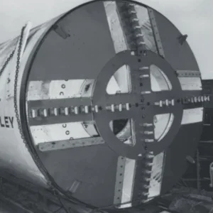
Liner installation, stability & removal
At the centre of each head location, holes for the steel liners were excavated,10 using a drill mounted on an offshore jack-up vessel (JUV). The liners were then lowered into position using a crane.
Once placed into the ground, the extrados of each liner is surrounded by high strength low shrinkage grouts with a shear key formed from a local enlargement into the rock. The shear key is crucial to the design. Therefore, to be conservative, any stability contributions from skin friction were ignored for the ultimate limit state design cases.
When a liner is reached by pilot tunnel, driven from the segmental tunnel, stability checks are then undertaken using multiple distinct monitoring techniques. Fresh water was added into the liners to resist buoyancy forces that would otherwise be generated by an empty shaft during initial offshore installation. Once it is determined through the DRMs that a liner is stable, it is then confirmed as acceptable through a RESS to drain the water, in a controlled manner using pre-installed valves.
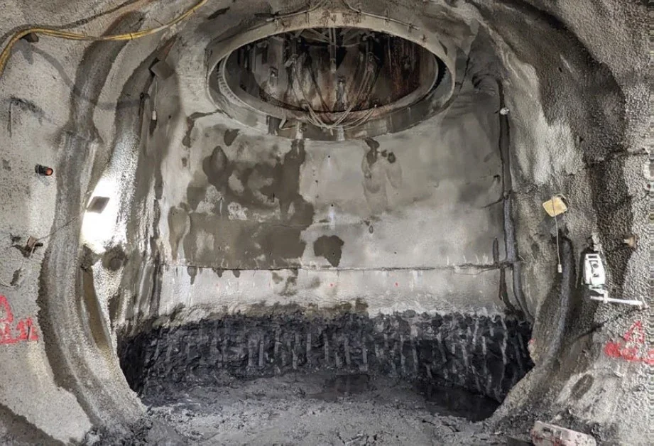
Using hydro-cutting, the bottom third of the 35mmthick liner has to be removed to make room for the SCL enlargement for the PW envelope.
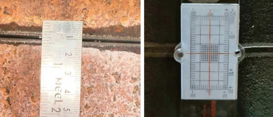
Once the initial horizontal cuts are undertaken in each liner, it is critical to understand if the shear keys are functioning as designed and that no significant vertical movement is occurring. In conjunction with SAA and precise levelling, this can be achieved using calibrated rulers, vernier callipers or preferably using instruments such as tell-tale precision gauges, which can be attached either side of the cut lines (see Figure 8).
To break the liner into manageable sizes, further partial horizontal and vertical cuts are made. The final short cuts are made immediately prior to individual panels being removed with overhead lifting equipment.
Tunnel enlargement & back mining
Following the sequential removal of the steel panels, the remainder of the adit must be enlarged to the required final profile. As this paper is written, the plan is for this to be done for the first two TSC locations in the first quarter of 2024, using a staged back mining process. Once this is complete, the PW installation can begin.
Change management
Due to the complex nature of the TSC (including nuclear safety requirements), and changes in personnel within the site teams delivering it compared to when the design was initially developed, multiple different approaches were considered to build the TSC TW. As significant steps had to be overcome to achieve initial design approval (see above), it is important that any proposed post-design acceptance changes are only progressed where there is an overall construction benefit.
To control the processing of potential changes, I instigated and lead bi-weekly request for information (RFI) meetings with BB and BeMo to consider future planned works in a timely manner.
When RFI responses are required, I am responsible for prioritising the multiple topics whilst also considering any PW changes, and either developing or reviewing the proposed responses prior to formal response to the RFI.
Where suitable, I have encouraged the collaborative review of RFIs between the TSC teams.
As the construction of the TSC TW is still ongoing, lessons learnt sessions will be held periodically and, where agreeable, changes implemented for the remaining locations.
TSC PERMANENT WORKS
The PW of the MW must be capable of operating for a planned working life of 85 years with limited future access due to operation of the power station. They are formed from cast insitu RC (high strength and low watercement ratio) structures, which considered a significant number of design cases to account for construction, operation, and maintenance scenarios that may be encountered.
Following the completion of the majority of the HPC onshore tunnels and shafts, I shared the lessons that
I had learnt for inclusion within the TSC PW designs. The primary lessons to aid construction were: suitable construction tolerances should be defined; tunnel specific concrete mixes should be developed; the requirements for preparation and waterproofing of construction joints must be clear; and, TW profiles must be controlled to avoid unforeseen impacts (e.g., cracking, clashes or design over-utilisation).
This paper does not include lessons learnt from the construction of the TSC PW as, at the time of writing this paper, the works are due to start in the first quarter of 2024, upon completion of the SCL TW.
Geotechnical & structural design
The ground loads acting upon the PW TSC were determined using PLAXIS 3D modelling and applied into SAP2000 3D structural models along with the required geometry, concrete properties, internal and external water loads, and seismic loadings.
Once the resultant stresses within the structures had been determined, concrete design calculations were undertaken in accordance with the works information, EC211 and other applicable design standards. This determined the reinforcement required.
Due to the geology, the impact of potential rock wedges was also assessed using UnWedge which is a 3D stability analysis and visualisation software program. Should potential wedges be identified by geologists, during excavation of the TW, they are locally spotbolted to hold them in place.
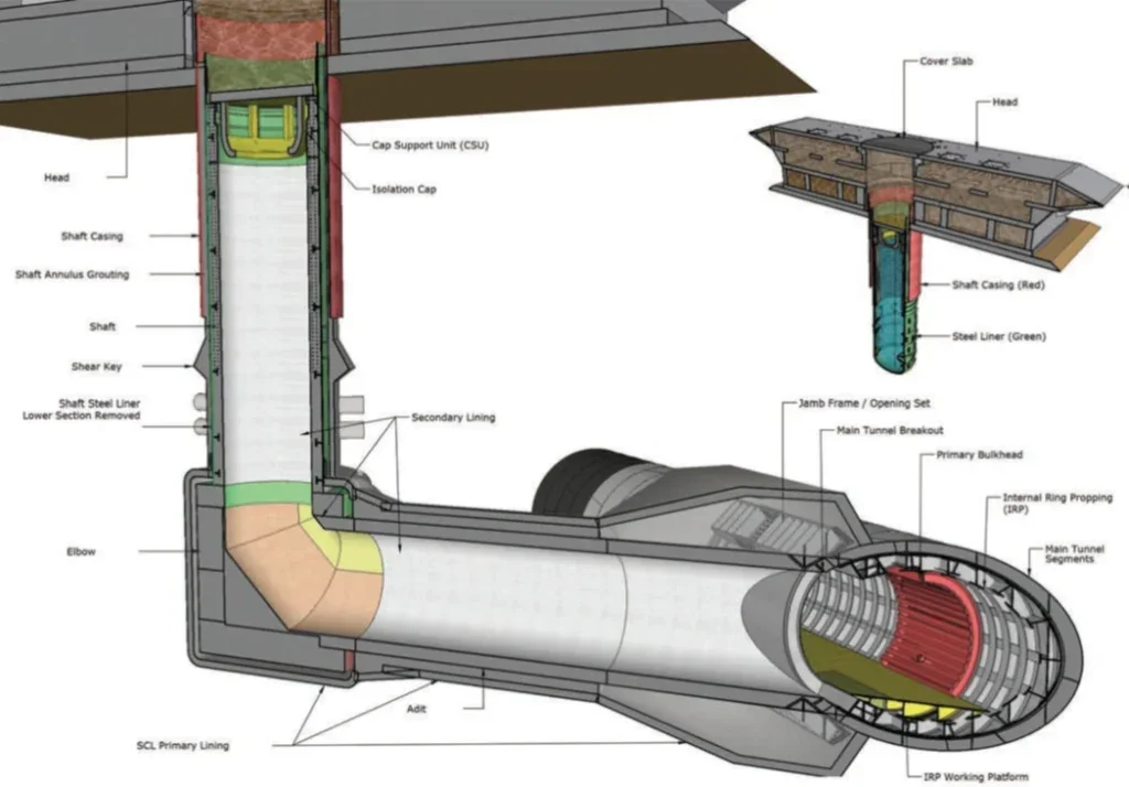
Geometry & space proofing
The geometry of the TSC is a balance between providing sufficient space for the PW, limiting excavation volumes, reducing overall complexity, and managing risks.
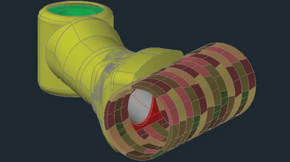
Due to the complex geometry, the PW of all TSCs has been modelled in 3D as shown in Figure 9. These models were produced using AutoCAD for both general arrangement and RC drawings and were beneficial for planned and unplanned activities, including activity scheduling and pricing.
When designing a TW SCL tunnel that is to have a PW lining, an additional space proofing tolerance should be included beyond any extrados cover zone to reinforcement. This should be considered from the outset and included within design calculations for both the TW and PW. A minimum additional extrados tolerance of 100mm is recommended.
Onshore shaft prefabrication
In the Royal Portbury Docks, in which I was based for several months to support BB, onshore prefabrication works were undertaken within the vertical section of the shafts prior to them being loaded onto a JUV and installed into the seabed.
PW reinforcement was preinstalled within most of the liner height and the uppermost concrete pour was undertaken to allow the isolation cap to be installed. Through joint site inspections, I helped to resolve construction queries which enabled the structures to be signed off and for offshore installation to begin.
The prefabrication allowed works to occur concurrently in different locations whilst also reducing risks associated with working in underground confined spaces, such as the TSC. Due to the nature and isolation of the TSC, other scope for prefabrication is limited.
Concrete mixes, assurance & quality
As the concrete must be batched onshore and transported a significant distance – both vertically and horizontally, underground – a long open life and workability is required, ensuring the mix remains useable and design compliant at the location of the concrete pours.
This has been achieved through use of concrete additives, such as ground granulated blast-furnace slag (GGBS), microsilica, superplasticisers, retarders, and extensive trialling. To ensure the design intent is met, I have developed a close working relationship with the BB materials team to understand its requirements and to provide support.
In the HPC onshore works, multiple strike cubes per pour have typically been relied upon to understand the strength gain within a concrete pour over time. As they are more exposed to external influences, strike cubes can behave variably compared to the concrete pours they are taken from, which would be significantly greater in volume and thickness, and therefore thermally act differently.
For use on the TSC, to improve quality assurance, reliability, and to reduce the required time before striking of formwork, a constant in-situ monitoring system (maturity modelling) is being developed by BB with support from myself and the Jacobs materials team. This system also provides safety benefits as it reduces the need for workers to prepare and retrieve strike cubes.
As the SCL surface is rough, it creates high restraint between at the interface of the PW concrete as it cures. This can lead to non-compliant cracking which would need repair.
When designing the TSC PW, the latest crack control guidance has been followed in accordance with CIRIA C766.12 This has required balancing the provision of crack control reinforcement (which may only be partially required for structural purposes) with limiting that likelihood of non-conformances.
Following my participation in a training session with the author of CIRIA C766, I investigated means of reducing early thermal cracking that was occurring within the onshore tunnels. This led to the installation of a debonding layer onto the SCL (see Figure 10).
In the onshore tunnels, the SCL debonding membrane was shown to be an extremely effective means of eliminating non-compliant cracking and achieving right first time construction with relatively low reinforcement densities; thus, reducing repairs required and the cost and schedule impacts associated with them. It was therefore taken forward for optional use within the TSC.
Joint preparation & waterproofing
In the onshore tunnels, due to access constraints and pour methodologies, it was sometimes difficult and time consuming to form a rough key on horizontal construction joints. Therefore, for the TSC, the design requirements have been reviewed and less stringent criteria considered, including options to coat the intrados of joints where mechanical roughening of the full joint is not possible.
When installing the construction joint waterproofing measures, there could be wet or dry conditions depending on the ground conditions. Therefore, to ensure products function as intended, options for each case were developed in close collaboration with material manufacturers.
To meet the designated leakage class requirements, water bars have been prescribed at vertical construction and movement joints. Due to the high water pressures to be resisted and seismic movements, I have previously helped to substantiate that specific products were suitable within the MW tunnels.
Optimisation & change management
Following preliminary trialling of the most complex reinforcement arrangements in the TSC, optimisation of reinforcement provision has been undertaken to improve buildability.
Further lessons learnt will be captured as the works progress.
As the original PW designs required detailed design substantiation, for post acceptance design changes to be implemented there must be suitably detailed justification developed, and accepted by NNB.
In my previous design coordinator role and now in my role as design manager, I have led the development of PW ‘field change requests’ (FCRs). In a controlled manner, this enables the accepted designs to be gradually improved upon to capture lessons learnt or to overcome adverse or unexpected conditions encountered in the field.
CONCLUSIONS
On the MW, I facilitated collaboration between the designer, contractor, and client to enable complex design and construction issues to be overcome whilst ensuring the project’s overriding nuclear safety and culture requirements are met.
As outlined by this paper, technological advancements have already and will continue to provide enhancements to space proofing, de-clashing, sequencing, remote excavation, and other elements of tunnel design and construction. To be successfully implemented, these technologies require an experienced team with a clear quality vision for the project.
From the different aspects of the MW that I have been involved in, to ensure the successful delivery of complex infrastructure, the critical requirement for success remains early engagement, open communication and collaboration within the team delivering it. Without this, even the most technically advanced project will struggle to succeed.
On design and build projects like the MW, this is best achieved through continuity of the construction team from design into construction with the support of knowledgeable design representatives embedded within the team. The regular sharing of knowledge and implementation of lessons learnt within and between projects should also be facilitated.
ACKNOWLEDGMENTS
At the near culmination of my involvement on the HPC MW, I am extremely grateful to all my past and present project colleagues who have given me the opportunity to learn from them over the last decade to enable me to become the collaborative engineer I am today
QUESTIONS & ANSWERS: SUMMARY
Following his presentation, David Maddison took questions from the BTS judging panel and the audience.
Questions began by seeking more insight into the waterproofing – techniques used, specification, and the required watertightness for the tunnels. In the discussion, specific to the tunnel to shaft connections (TSC), the operational need was noted as having limited requirements compared to other structures that have been designed having full waterproofing membranes. A challenge was noted, though, of placing waterstop bars and hydrophilic strips, especially at the sharp 90° elbow where there is significant rebar density. Discussing more achievability with the contractor rather than having Non Conformance Reports (NCRs) that need to be resolved.
At the time of the paper being presented, in March, the status of the activities was still in the temporary works (TW) stage, and leakage that is present is in terms of the intended pressure relief arrangements, draining the groundwater. The permanent works (PW) had yet to commence.
Further on pressure relief, it was explained that among the discussion points on site was the need to emphasise the design concept of pressure relief of groundwater in the bedrock, providing a dewatered zone for the TW stage of the tunnelling works. For that design strategy to be maintained in practice, discussions with the contractor focused on the importance of ensuring that the pressure relief holes (PRHs) were kept open, unblocked, uncovered, undamaged, and to continue to function.
It was added that waterproofing was worked well on the onshore tunnels, and where there was leakage along construction joints that gradually diminished, as the areas selfhealed, to be in line with required limits.
Questions also considered trends in innovation, and David noted that when he first started work in a design office no one was particularly using 3D modelling. But much more use of those have been made, and it is especially helpful in the TSC layouts where the geometry is too complex for 2D design approaches – without incurring follow-on problems of adjustments, NCRs, etc, during construction. There is coming to be more alignment, in general, on the benefits of using such models.
In summary, the design has worked quite well so far, and lessons being transferred or embedded (such as updating TW drawings) and recognition of benefits of purposeful collaborative engagement across teams. Though, with the project still in the TW stage it can be noted that while benefits come in achieving continuity, in both strategy and information, this can be a challenge as it often relies on people and – as is common in the industry – they move around.
On early career progression, advice offered to others, and current university students, include: seek mentorship; grab opportunities where you can; dive in and immerse yourself in projects and site; and, there’s luck, while also knowing you have to fight for yourself a bit. In summary, engage – full-on.
Last, absolutely not least, and perhaps speaking on something for all, a recommendation: produce the ‘lessons learnt’ in tangible form; make them visible such that others can readily read and see, and understand, and use them, and spread the benefits. Make them demonstrably real, as a practice.