The progression of the US$823M Lane Cove Tunnel Project has been rapid, following planning approval in 2002. Tenders were submitted in January of 2003 and following a period of bidding and negotiations, the New South Wales Government entered into an agreement with the Lane Cove Tunnel Consortia in December 2003 to design, construct, finance, operate and maintain the project as a toll road. A joint venture of Australian contractors, Thiess and John Holland are delivering the project under a design-construct contract. Parsons Brinckerhoff (PB) is the lead designer for the tunnels and the civil structural components of the project.
In addition to the tunnelling work, the project spans over 8km of surface roadway improvements through a congested roadway corridor, passing through residential and industrial areas in north west Sydney (figure 1). The benefits of the project include reduced travel time, reduced congestion, improved public transport and improved neighbourhood amenities for pedestrians and bicycle users.
The scheme design began in December 2003 and is now at a mature stage. Tunnel design will be completed before Christmas 2004.
The project is being delivered under a rigorous quality assurance program involving both internal and external review by the Roads and Traffic Authority (RTA) and an independent verifier. The first temporary access tunnel design was approved in time for construction to begin in May 2004 from the western end and the second in July from the eastern end. The first permanent tunnel design was approved in time for mainline tunnel construction to begin in August.
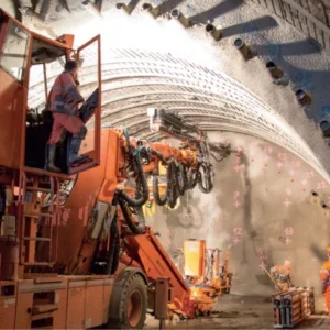
By mid-September additional design had been approved and four roadheaders are now operating at three locations. Altogether, seven 300kw roadheaders are scheduled to excavate the tunnels, two Mitsui SLB 300 and five Voest Alpine ATM105 (figure 2). The mechanised drilling and installation of rockbolts is performed by either an Atlas Copco Boltec LD unit or a Boomer 135/352.
Tunnel design overview
The 3.6km long east-bound and west-bound tunnels comprise the signature features of the Lane Cove Tunnel Project. However, a labyrinth of additional underground ventilation and emergency egress tunnels are also required to meet stringent operational congested mode and emergency scenarios.
The eastbound tunnel provides two traffic lanes in a cross sectional area ranging from 53.27m2-58.49m2, from the western driven portal to a point just east of Stringybark Creek. Here the tunnel widens to 76.26m2 to accommodate three traffic lanes for a distance of 1500m, and then a lane diverges as an exit ramp to the Pacific Highway, whilst the two main lanes continue to the eastern portal. The exit ramp will be some 450m long, and comprises two traffic lanes.
The westbound tunnel starts as a 53.27m2-58.49m2 two lane tunnel from the east portal, and is then joined (after a distance of approximately 600m) by an entry ramp from the Pacific Highway. Following the junction with the entry ramp, the tunnel becomes a 76.26m2 three lane carriageway all the way to the west portal. The entry ramp will be approximately 350m long, and comprises one traffic lane with a 2m wide emergency stopping lane.
Pedestrian cross passages/emergency egress are provided at a maximum spacing of 120m, in accordance with the project egress requirements. The cross sectional dimensions of the passages are about 5m wide by 3.9m high. Two vehicular cross passages, with fire rated roller shutters, are provided at one-third distances in the tunnel for access for emergency vehicles during an incident. These cross passages are sized to allow a single unit truck to negotiate a U-turn from one tunnel to the other in one pass.
Two ventilation tunnels will connect the main tunnels to ventilation stacks located at Marden Street and Sirius Road. These ventilation tunnels will be approximately 60m2 and 90m2 in cross section respectively, to meet ventilation requirements, and are about 500m in length. The Marden Street ventilation tunnel will extract vitiated air from the eastbound tunnel and the Pacific Highway exit ramp. The Sirius Road ventilation tunnel off-take from the main westbound tunnel will be located at a distance of approximately 1360m from the west portal, and the tunnel will be about 500m in length with a low point below the crossing of Stringybark Creek. At the end of the Sirius Road ventilation tunnel, a 35m deep vertical shaft will provide access to the surface.
A separate ventilation exhaust tunnel is provided below the westbound carriageway to remove vitiated air from the east and westbound tunnels. The exhaust ducts for these carriageways are located upstream of the inlet vent tunnel at approximately the mid point of the tunnels.
The exit and entrance ramps to the Pacific Highway require emergency egress provisions at 120m spacing capable of wheelchair egress, similar to the mainline tunnels. Since the ramps are closer to the surface than the main lane tunnels, emergency egress is provided between the exit and entrance ramps by using separate passages in the adjacent ventilation tunnels to provide egress.
Driven tunnel and cut & cover
The Lane Cove tunnels are predominantly driven tunnels, with cut and cover sections at each end of the main lane tunnels and the portals of the ramps. The main lane tunnels have common cut and cover structures at both the western and eastern ends. The western cut and cover structure is located east of the Mowbray Road intersection in Epping Road. This portal section will involve bored pile and top down construction within a staged excavation.
The eastern cut and cover portal is located in the middle of the Gore Hill Freeway, immediately west of the Reserve Road fly-over. A short cut and cover box is required to facilitate the transition from driven tunnel to a deep cutting. The cut and cover box will be approximately 75m long and 15m-20m deep. A secant pile perimeter wall supported with up to four levels of ground anchors will be used to support the excavation until the tunnel roof and floor slab is constructed. The excavation above the cut and cover tunnel will then be backfilled and landscaped.
The westbound entry ramp from the Pacific Highway joins the two lane west-bound tunnel 200m west of the Pacific Highway, via a portal and decline on the eastern side of the Pacific Highway beneath Alto place.
The east bound exit ramp to Pacific Highway reaches the Gore Hill Freeway in a deep cutting.
Geotechnical conditions
The tunnels will be excavated in the upper sedimentary formations of the Sydney Basin stratigraphic sequence, which consists of sub horizontal beds of middle to early Triassic aged rock comprising Hawkesbury Sandstone, Mittagong Formation and Ashfield Shale.
The Hawkesbury Sandstone formation is well known as a good tunnel medium, comprising predominantly fine to medium grained quartzose sandstone deposited in 1m-3m thick beds and lenses that exhibit either massive structure or foreset cross beds dipping at 20?-30?. Erosive contacts are common between beds, and shale breccia channel lag type deposits are observed at the base of some beds. Shale (siltstone) interbeds and lenses make up a minor part of the sequence.
The Mittagong Formation is typically 5m thick and comprises interbedded sandstone, laminate, siltstone and claystone and is the transition from the Hawkesbury Sandstone and the upper Ashfield Shale. The Ashfield Shale comprises dark grey to black laminated carbonaceous and calcareous siltstones and mudstone with rare sandstone laminae.
Typically the bedding planes are subhorizontally bedded, although steeper bedding can be encountered in the Ashfield Shale. The spacings between bedding planes in the Hawkesbury Sandstone is typically 0.5m-3m. Joints are typically discrete and contained within individual beds, approximately 15% have a vertical continuity of about 5m or more. The major joint sets in the Hawkesbury Sandstone trend north-south and east-west with a subordinate northwest-southeast set.
Design parameters were developed on the basis of geotechnical information available, supplementary project specific exploration was carried out, and geological experience in the Sydney Basin environment was used to develop the design parameters for the various geological strata and defect types.
Driven tunnelling conditions
The majority of the tunnel in the western half will be within Hawkesbury Sandstone. From the tunnels mid-point to the eastern portal, the tunnel horizon comprises the Mittagong Formation, and the lower member of the Ashfield Shale. The tunnel traverses through all the above formations and is expected to encounter zones of inferior rock associated with faults, shale interbeds, volcanic dykes and joint swarms. Heavier support will be required to these areas.
The first 275m of tunnel from the eastern portal positions the tunnel crown within about 4m of the floor of a back filled brick pit. The quality of the rock beneath the brick pit is assessed to be typically good, but may be fractured as a result of blasting/excavation of the shale during operation of the brick pit.
Probe drilling and grouting will be carried out for the 200m section of the tunnel in this area. Appropriate contingency measures are being developed, with grouting expected to be used if short-term dewatering of the backfilled brick pit would result in unacceptable surface settlements.
Where a tunnel crown is located in sandstone possessing near-horizontal bedding planes and characteristic joint sets and typically regular joint spacing of between 2m-5m, the tunnel will have a flat arch roof. The temporary and permanent support consists of rockbolts, whose length is largely dependent on the span. The tunnel sidewalls are excavated as vertical walls thereby completing the 53.27m2 cross sectional area designed for two lane stretches.
Where the crown is located in the shale formation, a higher arched tunnel crown will be constructed giving a larger 58.49m2 cross sectional area in the two lane tunnel length. At the junction of the Pacific Highway exit and entry ramps with the main tunnels, the excavation profile requires spans of up to 21m.
A rock pillar of sufficient width is required to carry the rock load without being over stressed. These substantial spans require significant support in the form of rock anchors, steel fibre re-inforced shotcrete and lattice girders. Cable bolts will be installed for the rock support in the ramp junction areas. The tunnel junctions are located in Mittagong Formation and Ashfield Shale.
Low cover occurs in the eastern end of the tunnels beneath the Artamon brick pit and in the entry ramp. Depending on the characteristics of the rock mass encountered at these critical sections, the support selected will take one of the following forms:
Tunnelling methods similar to those used in soft ground may be adapted to tunnel beneath the brick pit fill at the eastern end of the tunnel. These methods may comprise spiling bars or canopy tubes, sequential heading and bench, lattice girders, steel sets, FRS, ground treatment (grouting). Support requirements will be derived based on detailed analyses of the ground loading and settlement criteria.
Design methodology
The design methodology that has been utilised began with the development of geotechnical long-sections and cross-sections to assess the likely rock block sizes to be encountered. A study of precedent practice of large-span caverns in Hawkesbury Sandstone and similar strata was performed to establish precedents for roof support requirements and measured deformations. There was a comparison of empirical guidelines for large-span tunnels in horizontally bedded strata. Analysis was performed using Voussoir beam methods and bedding plane shear reinforcement concepts.
Numerical modelling was performed to investigate the rock mass response with the support levels indicated by the analytical study. This modelling was typically used for wide span junctions, jet fan enlargements, intersections in typical and adverse rock conditions, and excavation and support sequencing. Analytical and numerical studies were also performed for secondary openings, junctions and passageways.
In the analysis of the flat bedded roofs, the stability of the tunnel excavation within horizontally bedded strata was analysed by considering the performance of a single roof beam deflecting under its own weight and an allowance for surcharge loading. The subsequent design of rock bolt support involved the assessment of shear displacements along horizontal bedding planes. The fundamental requirement of the design process was to control the shear displacements along bedding planes within the required thickness of the ‘linear arch’ assumed to form in the strata.
The rock bolt reinforcement thereby artificially ensures that the thickness of the roof beam is sufficient for the beam to become self-supporting. Numerical analysis was performed utilising either Phase² or FLAC. The numerical analyses using Phase² software was used to assess the tunnelling-induced ground movements and stresses.
In the arch roof, Phase² modelling of the typical roof construction was performed. It was important to reflect the geotechnical conditions, and examine the effects of the staging of excavation and installation of supports. The effects of shearing at the haunch in the arched roof sections in shale was examined in greater detail. Considerable numerical modelling was performed. Geotechnical sections for numerical modelling were selected based on various geotechnical profiles, overburden thickness, surface structures and special geological features. Models were set up to represent possible tunnel configurations and geological conditions along the tunnel alignment.
General aspects of the analytical modelling included parametric studies using generic models in Phase². Its aim was to assess the impact of various geometric and geological features on the tunnel designs and to identify critical design parameters/conditions. Phase² was also used to address specific design issues during the initial modelling stage. In particular, the sensitivity of in situ stress state and tunnel geometry on tunnel and ground surface displacements was studied. Two geological domains (typical and adverse conditions), tunnel support systems, specific structures and construction sequences were analysed as appropriate.
Construction requirements
Construction access to the eastern end of the driven tunnels is provided through the excavation of the eastern ventilation tunnel and access adit from Marden Street, which joins the mainline tunnels.
The adit may be used to house equipment for the permanent works and during the tunnel operation phase it may also be used as a permanent access for emergency vehicles to gain access to an incident in the tunnel.
Construction staging
As can be gathered, the tunnels will be major excavations in rock. The rock mass response to the excavations will be dependent to a large degree on the excavation sequence adopted. It is therefore a key requirement that the tunnel design is progressed in close liaison with the construction planning team, and that construction sequencing forms an integral part of the design.
The excavation staging takes into account the plant and equipment to be used by the contractor. For example, all excavation stages must be dimensioned to suit the requirements of the principal roadheader excavation plant in terms of advance lengths and reach, etc. Similarly, the rock support elements, in the form of rock bolts and/or cable bolts, will be installed close to, or at specified distances from, advancing faces headings.
Related Files
Fig 1 – Plan diagram of the Lane Cove Tunnel project
Fig 2 – Plan of the tunnel systems with roadheader excavation sections marked up