Ground freezing was specified on the Bergen Point Wastewater Treatment Plant in West Babylon, New York to provide groundwater control and temporary earth support at both launch and receiving shafts. This was preferred to the other options available which included freezing, diaphragm slurry walls and secant piles.
The excavated diameter of the launching shaft was 9.1m to a depth of 38.75m. Designing a ground freezing system brought two unique challenges. The most significant was the absence of a confining layer at the shaft invert, which would result in vertical groundwater flow into the shaft during excavation and complete bottom instability, leading to basal failure. The second challenge was the potential existence of lateral groundwater flow exceeding one metre/ day. High groundwater velocity can retard and in some cases prevent the formation of a frozen earth structure.
To prevent stability failure at the shaft invert level, the design incorporated a frozen base to the excavation. The shaft was frozen solid approximately six meters below the excavation as illustrated in Figure 2.
Pipe Geometry
Figure 1 shows the refrigeration pipe geometry. This includes the 1m-spacing of the perimeter pipes with nine inner pipes arranged in a square/diamond formation to form the frozen base. The inner pipes were insulated to 38.75m to reduce the frozen ground within the excavation. A time-dependent heat transfer finite-element model confirmed that the inner pipes could be discarded during the excavation. Once the base was frozen, the perimeter pipes provided enough refrigeration to maintain the freeze. In fact, the modeling showed that the base would continue to get increasingly colder even after the inner pipes were removed.
The thermal model was then coupled with a hydraulic model that included a lateral groundwater flow of one metre/day. Refrigeration pipe spacing, circulating coolant temperature and freezing time all contribute to the ability of a ground freezing system to form a frozen earth structure when subjected to lateral groundwater flow. The model confirmed that the specified pipe spacing, and a -32oC coolant temperature would form the frozen structure in approximately six weeks.
Ensuring Adequate Frozen Earth
While the geotechnical baseline report included frozen soil compression tests, additional tests were conducted for strength confirmation. The results of these tests were used in a numerical structural analysis to evaluate the required thickness of the frozen earth. It was determined that a 2.5m frozen earth wall would provide a safe structural and watertight excavation. The contract specifications required that a temporary shotcrete lining be installed as the excavation progressed. A structural analysis demonstrated that the frozen earth structure could support the entire depth of the excavation if combined with sufficient insulation. The lining could therefore be installed from invert to the ground surface.
Refrigeration pipes were drilled and installed using a mud rotary drilling system. After drilling to the required depth, the drilling steel was removed, and the 114mm-diameter pipe installed. Pipe connections were welded at the joints as well as welding an endcap at the base. After each pipe was installed, it was pressure tested and surveyed for verticality. Any pipe that did not meet the requirements of the design was either repaired or replaced.
Each pipe contains a smaller diameter HDPE feed tube extending to the bottom and fitted with a custom-made freeze head at the surface. The refrigerated brine flows from the supply manifold, down the inner tube, and returns to the surface as shown in Figure 3. As the cold brine flows upward in the annulus, it extracts heat from the ground and rises for subsequent recirculation. Now a warmer brine, it flows through the return manifold, back to the refrigeration plant where it is cooled and returns to the pipes for another cycle.
A key component of any ground freezing system is the coolant flow. There have been several ground-freezing projects in the past 40 years that met the requirements of pipe spacing and coolant temperature but neglected to provide sufficient flow to each individual refrigeration pipe. The coolant used on this project was a 28% calcium chloride solution. The design required a minimum flow of 6.8m3/hr through each pipe or group of pipes. A hydraulic analysis of the system was conducted to ensure that there was sufficient pumping capacity.
Cooling the calcium chloride brine required the use of two mobile refrigeration plants. These use anhydrous ammonia as a primary refrigerant to cool the brine via a heat exchanger. Each plant has a refrigeration capacity of 310kW at -30oC and was powered by diesel generators. The formation of the frozen earth structure required two of these refrigeration units. Once the structure was formed, only one plant was required to maintain the freeze.
Instrumentation
Instrumentation is the key ingredient to ensure the success of any ground freezing system. An integrated system that measures in real time and records the data was used on this project. It comprised three main components.
Ground temperatures were measured at seven locations within subsurface temperature-monitoring pipes. Each of these pipes was drilled and installed in a similar way to the refrigeration pipes.
Some pipes were installed at an angle to measure the temperature regime through a section of the frozen earth wall. When completed, they were filled with the calcium chloride brine, but not connected to the system. Within each of the pipes a string of thermistors was installed at 1.5m intervals. The sensors used BeadedStream technology that has all the sensors connected to a common wire instead of individual wires. The wires were then connected to an input module that was monitored by the SCADA system. Ground temperatures were plotted daily and compared to the thermal models which enabled the temperature to be evaluated at any location, even though there was not a monitoring pipe.
Monitoring The System
System monitoring was the second key component of the instrumentation system. Temperatures of the circulating coolant were measured both on the supply line near the refrigeration plant and at the return line coming from each individual refrigeration pipe. Evaluation of the temperature difference between the supply temperature and the individual return temperatures allows the freezing engineer to evaluate the heat transfer and balance the flow of the system. Flow meters are also installed near the refrigeration plant to ensure that the design flow is achieved, ensuring efficient heat transfer from the subsurface soil to the circulating coolant.
Each refrigeration plant is equipped with sensors and controls to monitor the operation of the compressor, heat exchanger and evaporative condenser. These sensors have appropriate alarms and shut offs to ensure safe operation. Extreme care is exercised to ensure that in the event of any leaks of anhydrous ammonia, the plant is shut down, an alarm system is activated and safety personnel are notified.
The final component of the instrumentation system is the groundwater monitoring. Piezometers were installed around the exterior and in the centre of the shaft. Transducers were installed in each piezometer to permit real-time and constant monitoring of groundwater levels. This monitoring served several purposes. A difference in groundwater elevation across the site could indicate a gradient and a potential groundwater velocity of more than one metre/day. It should be noted that such a gradient was never observed on this project.
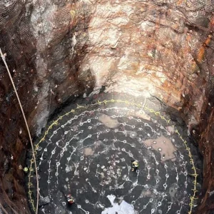
Comparing the external water levels with the levels measured inside the shaft provided an indication of the complete formation of the frozen wall. The groundwater on this project was subject to hourly tidal variations. When the frozen wall was completely formed, it provided an isolation between the internal and external piezometers and no variation was observed inside the frozen structure.
An interesting phenomenon is always observed in the internal piezometers on ground freezing projects. Once the frozen wall is formed and the interior and exterior piezometers are isolated, the frozen wall continues to grow and encroach on the centre of the shaft. When this occurs, pore water is forced to the centre of the shaft and the levels in the centre piezometers rise. In fact, they continue to rise until water is actually flowing from them. This is the best indication that a watertight frozen earth structure has been formed.
The groundwater levels illustrated in Figure 4 (left) are actual data recorded during the freezing process. Piezo 1 was the internal monitor while 2 and 4 were external to the shaft. Note on day 26 how the level flattened and did not indicate tidal influence. This is when the frozen wall was closed and formed a watertight structure. The rise in the level indicates the frozen wall getting thicker and forcing the porewater to the centre.
Once the frozen wall was formed, the excavation process was initiated. To meet the contract specifications, it was necessary to have a 3m-thick frozen wall. This was 0.5m thicker than the Keller design and resulted in the excavation of considerably more frozen soil. Frozen soil increases in strength with colder temperatures. As the temperature of the frozen soil continued to decrease, there was an observed increase in strength.
With the excavation progressing, it was necessary to apply polyurethane foam insulation to the face of the frozen ground. A wire mesh was attached to the surface and then approximately 50mm of polyurethane foam was sprayed.
This procedure was necessary over approximately 3–4m of the excavation. Once the excavation had reached the required depth, a concrete mud slab was poured, followed by reinforcing steel and the base slab. Shotcrete was applied from the bottom up to the surface. Once the shotcrete had cured, the freezing was turned off and the tunnel boring machine (TBM) lowered into the hole.
Excavation is currently proceeding on the receiving shaft awaiting the expected arrival of the TBM.