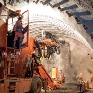
The tunnelling industry has been waiting for a reliable continuous TBM mining system for decades. In the conventional method for soft ground tunnelling, forward progression is stopped for installation of the segmental lining. In rock tunnelling, a double-shield TBM must be used to enable continuous mining; thrusting from the TBM grippers while segments are being erected behind them. In addition to requiring a more expensive double-shield TBM, any difference in rock stiffness beneath the left and right grippers can create challenges in steering the TBM resulting in reduced success when attempting continuous tunnelling in soft rock.
Using the proposed method, all the aforementioned concerns are addressed. The author’s patented system employs a single helical segment that is installed continuously as the TBM thrusts forward (see Figure 1). Nearly all the TBM’s thrust cylinders are used in pushing against the segments with the exception for those that would thrust against the segment that is being erected at any given time. This allows the TBM to progress forward while a segment is being erected in a continuous manner that is expected to increase tunnelling speed significantly, up to twice the speed in certain cases.
The segments are universal (of like size) and have short projections on the two trailing edges (circumferential and radial) and similar recesses in the opposite two leading edges. This forms a tongue-and-groove joint at both circumferential and radial joints. These joints interlock naturally and no other connection is required, however this system provides the option to insert a post-tensioning (PT) strand into a continuous groove located at the base of the leading circumferential edge recess as shown in Figures 2 and 3. The proposed helical tunnel lining method allows PT strand insertion to be completed continuously and autonomously.
Similar to conventional segmental linings, the TBM thrust cylinders will temporarily support each segment until the PT strand is inserted and the next segment is erected. The TBM thrust cylinders would be operating at different extension lengths to push uniformly against the helical leading edge of the segments. It may be necessary to reduce or remove thrust force on the segment located on the side opposite that of the segment being installed to better balance the thrust forces for TBM steering.
There are practical limits on the length of tunnel that can be constructed using a single length of PT strand. These include supply and tensioning length limits on the strands, project scheduling, and other constructability concerns. A special socket segment can be employed for terminating one strand and beginning another. Such a segment would include two pockets with conduits that cross over each other before emerging into the PT strand groove. The leading pocket is used to terminate the previous PT strand while the trailing pocket is used to begin the next PT strand which has been shown in Figure 4.
An alternative method for anchoring a PT strand that does not require a special socket segment is anchoring and tensioning the leading end of the strand using a temporary steel frame then grouting the PT strand groove. Once the grout has cured, the temporary frame may be unloaded and removed as the PT strand tension will be locked in to the segmental lining structure via the grout.
The temporary steel frame can be eliminated if the PT strand is placed autonomously where it is continuously tensioned by the TBM and grouted at regular intervals. An additional recess within the PT strand groove located near the center of the segment would provide clearance for a coupler connection between the previous and new strands wherever required.
Two options have been considered for introducing alignment curves to the helical segmental lining. The first requires the use of tapered packers placed within the circumferential edge recess as shown in Figure 5 and 6. The second requires the use of length-modified segments, not unlike the conventional tapered segments currently in use; however, this option contradicts the universal concept of the helical tunnel segment.
The tapered packers could be manufactured from several materials including, but not limited to vulcanised rubber, GFRP, and steel. Tapered packer thicknesses would be expected to range from 4mm or smaller to 24mm or more. The segment recess depth will limit the maximum allowable packer thickness whereas the minimum thickness is expected to be approximately 3-4mm due to practical constructability.
These packers would be applied to one side of the tunnel, inserted into the circumferential recess once the PT strand has been inserted. By installing specifically chosen thicknesses in consecutive circumferential joints, the tunnel construction may follow an alignment through any curve: vertical or horizontal, constant or compound, or any combination of the these (see Figure 7).
Different thicknesses of tapered packers can be stocked on a single project to allow a TBM to achieve different curve radii while maintaining packer placement within consecutive joints. This aids in the elimination of ‘missed’ packers. However, a single thickness packer may also be employed at certain intervals to achieve different radii like how tapered rings are employed in certain orientation patterns to achieve different curve radii. It is possible to reduce material costs by employing segmented packers rather than continuous packers (see Figure 8). These are placed at the TBM thrust cylinder locations only.
Waterproofing is achieved using one or two rows of gaskets on the sides of the segments’ trailing edge projections as shown in Figure 3. The gasket would function similarly to that of a bell-andspigot connection between precast pipes. Alternatively, the continuous tapered packers may be constructed of such a material and in such a manner as to function as both a gasket and a joint filler for completing alignment curves.
The shear key recess at middle of the universal segments are used by the TBM’s segment erector to enable pushing the segment well into its final position. It could be possible to eliminate the shear key recess as well by using vacuum erector along with TBM’s thrust cylinder to push the segment into its place. It is possible for current segmental TBMs to be adapted for use with helical tunnel lining segments. The primary alteration required is to modify the thrust cylinder shoes to include hinged and parallelogram plates to best fit against the leading circumferential recessed face of the segments.
Other than providing for continuous tunnelling, the helical PT system provides another advantage that the load induced by the stressed PT strand is applied in both the circumferential and longitudinal directions, effectively pulling the tunnel structure together.
Geometrically, the force from the thrust cylinders is applied to the segments in the direction parallel to the tunnel alignment and acts on a plane with an angle equal to the helix angle (i.e. the leading segment face). Thus, the thrust force will be the resultant of two component loads: the load perpendicular to the segment face and the load tangent to the segment face. The perpendicular load will push each segment toward the previously erected course and tangent load will push each segment toward the previously installed segment. The two component loads will thrust the segment in two desired directions helping to tightly close each radial and circumferential joint, and maintain stability of the tunnel structure.
The purpose-built helical tunnel lining TBM could be automated such that it automatically inserts the PT strand and any tapered packer as the tunnel advances. Further it is expected that a TBM may be able to automatically tension the strand continuously and grout the groove after a predetermined length of tunnel construction. Hence, with an optimistic vision from the Author and the comprehensive implementation of this system, it could be possible to minimise the underground human-element in the tunnel construction where the TBM and associated systems could be controlled from the surface – akin to microtunnelling – in a near future. Such developed intelligent tunnelling system might be suitable for the future space tunnelling as well e.g. tunnelling in Moon/ Mars.
MAIN ADVANTAGES OF THE SYSTEM
1) Higher speed:
1-1) Due to the elimination of the mining-stoppage for segment erection, the forward progress speed can be significantly increased and in certain cases doubled. TBM will obtain better and smoother performance without stopping and restarting for ring erection.
2) Lower costs:
2-1) Interlock system eliminates bolt connections between segments.
2-2) Elimination of bolts removes the need to fill bolt pockets. 2-3) Only one type and size of mould will be needed to cast all segments.
2-4) Thickness of the segment, tunnel outer diameter, and excavated volume can all be reduced due to improved moment strength capacity using PT strands.
2-5) Required reinforcement can be reduced due to the imposed pre-stress and increased strength of the segments. 2-6) Secondary concrete lining can be omitted due to the improved quality, durability, and resistance listed above. 2-7) In most cases, steel-fibre reinforced concrete would be sufficient for the design of the helical segments. However, some light bar reinforcement may be required at the leading and or trailing edges.
2-8) Due to the elimination of bolt connections, an automatic lining operation for inserting, tensioning, and fastening of the PT strands will be feasible.
3) Higher quality:
3-1) The lining’s intrados will be smoother and more continuous due to the elimination of the bolt connection pockets. 3-2) Segment pre-stress achieved using the PT strands will aid in the reduction of cracks, improving the water-tightness and overall quality of the tunnel lining.
3-3) Generally, the durability of the lining will be improved due to the increased quality.
4) Higher resistance:
4-1) Flexibility and resistance against seismic loading are improved due to the helical structure and pre-stressing of the segmental lining in both longitudinal and circumferential directions.
4-2) Resistance against squeezing rock will be improved as well due to the reasons explained in 4-1. 4-3) Extra resistance against breakage can be achieved in the joints between the segments.
4-4) As a result of the segment pre-stress and increased bending moment capacity, the resistance of the lining to internal water/effluent pressures as well as external soil or water pressures will be improved.
FEA modelling of various tunnel diameters and loads confirm the satisfactory performance of the helical tunnel lining system. (See Figure 9)
Similar to the current practice in the tunnelling industry for the conventional method, the following 11 load cases have been applied in on various helical segmental linings and satisfactory results are obtained:
Production and shipment stages:
1) Segment stripping from the mould 2) Segment storage 3) Segment transport 4) Segment handling
Constructions stages:
5) TBM thrust jack Loads on segment 6) Grouting pressure on segment within TBM tail shield
7) Localised grouting pressure on Segment
Final service stages:
8) Earth pressure, surcharge and Groundwater
9) Segment longitudinal bursting 10) Other distortion
11) Further loadings, e.g., earthquake The author predicts that this system would be employed widely for future tunnel projects due to its various advantages over conventional segmental tunnel lining systems. The illustrated helical tunnel lining system, its variants, and their proposed advancements are patent pending in several countries.
It is necessary to obtain the author’s legal consent to implement the system in any capacity.


