INTRODUCTION
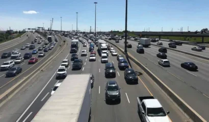
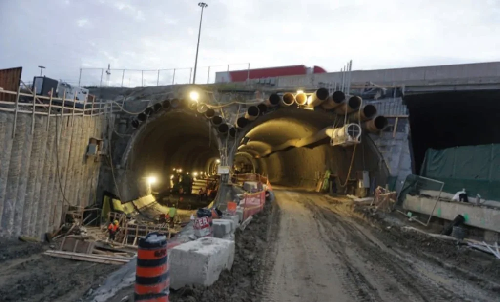
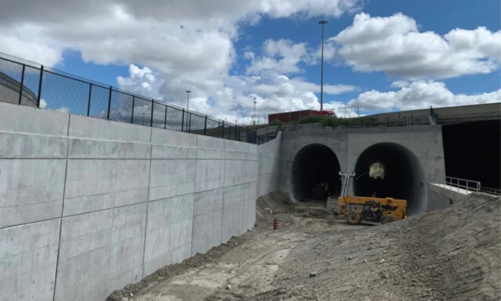
The Highway 401/409 Rail Tunnel Project in Toronto, Canada, was part of a larger initiative aiming to increase the capacity of Toronto’s commuter rail system. The project is located east of Toronto’s Pearson Airport at the intersection of Highways 401 and 409 and involved the construction of approach ramps and a 180m-long underpass to house two additional tracks beneath the 21 lanes of one of North America’s busiest highways, with daily traffic of approximately 450,000 vehicles.
The challenges posed by the live traffic, tight settlement limits, poor ground conditions and constrained space demanded innovative engineering solutions.
The client, Metrolinx, in collaboration with Infrastructure Ontario and the Ministry of Infrastructure, awarded the project to Toronto Tunnel Partners (TTP), a joint venture of Strabag, Inc., and EllisDon. The design and engineering services team was formed of Dr. G. Sauer & Partners (DSP) as tunnel designer, WSP as multidisciplinary consultancy, and Wood as geotechnical design specialists.
CONTRACTING AND PROCUREMENT PROCESS
The procurement followed a multi-phase approach involving contractor outreach, prequalification (RFQ), and a detailed Request for Proposal (RFP) process that lasted more than a year.
During the outreach, Metrolinx engaged contractors early in the process to discuss the project and solicit feedback on the proposed design and construction approach. The initial concept was presented to contractors, and feedback was gathered to understand the feasibility of the design. Also, acceptance of the Design-Build-Finance (DBF) approach, very commonly used in the Toronto area by Metrolinx, within the construction industry was confirmed.
Following an RFQ, contractors were prequalified based on their technical expertise, financial capacity, and previous experience with similar infrastructure projects. This led to an approximately one yearlong RFP process, where prequalified bidders were asked to submit detailed technical and financial proposals.

Given the project’s highrisk profile, managing financial risks became crucial. Contractors were responsible for securing financing and managing cash flows throughout the project, as payments were deferred until substantial completion. This financial arrangement required a robust contractual structure, similar to that used in fullscale PPP projects, to protect both the contractor and the client from potential financial exposure.
From a technical aspect, the project was opened to alternative solutions, allowing the contractor to explore more innovative tunnelling techniques. The evaluation criteria for the RFP phase were split equally between technical (50%) and financial (50%) considerations. This structure emphasised both innovative design solutions and costeffectiveness. Metrolinx typically provides a stipend for the losing bidders, in this particular case Can$400,000, as the development cost for such a design and build project are significant.
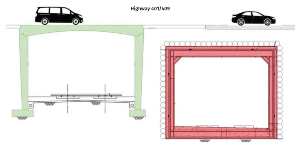
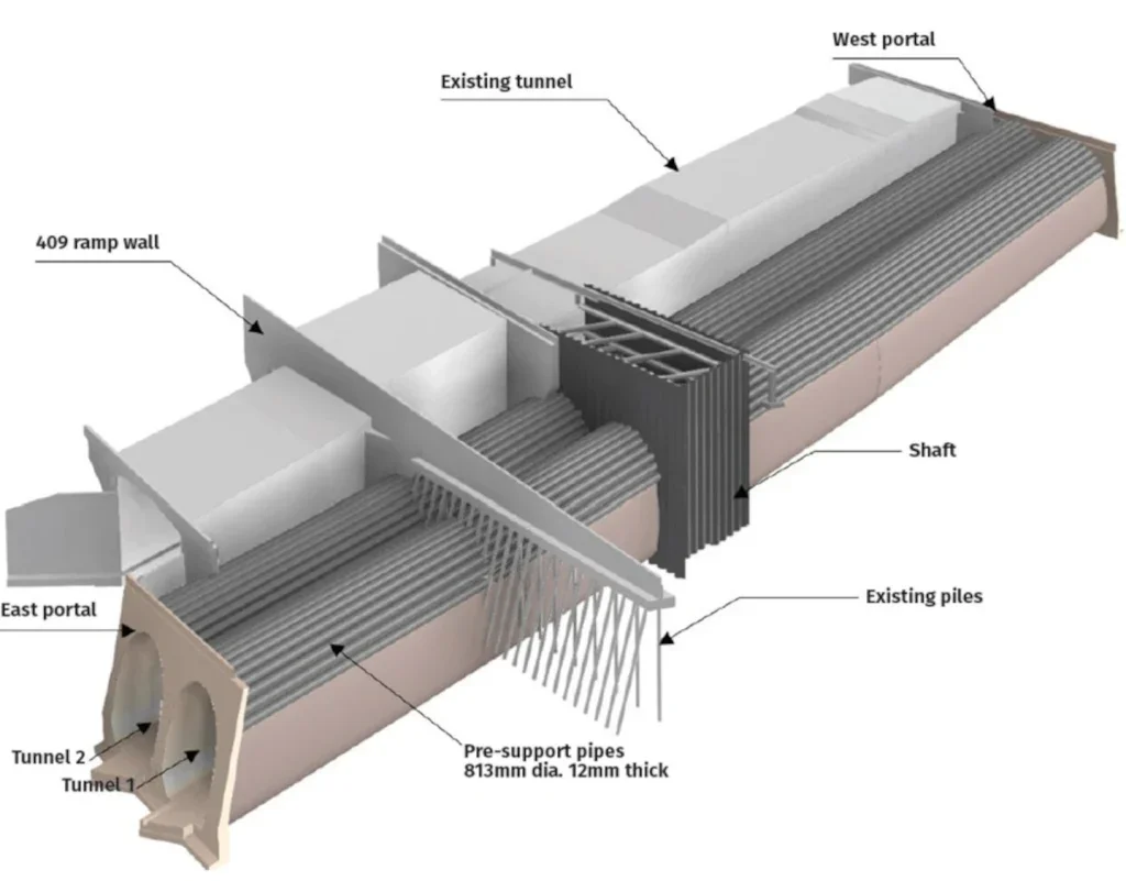
At the start of the RFP process, Metrolinx provided a Reference Concept Design (RCD) involving a single large box with piles drilled around the tunnel circumference forming the initial support (Figure 2) followed by a box being pushed through. The new structure was to be built next to the existing underpass which was established during highway construction in an open trench. During the RFP process, the client opened up to other construction methodologies than the method suggested in the RCD.
The major challenges to overcome were the low overburden, disturbance to the existing tracks and track alignment requirements to join the new tracks into the existing infrastructure, the tight settlement criteria on the road and existing structures, and very specific criteria imposed on the construction methodology for presupport installation.
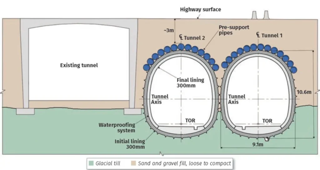
TTP initiated a comparative assessment process to evaluate various alternatives. Several tunnelling methods and designs were assessed based on their technical feasibility, cost, risk profile, and schedule (Figure 3). The outcome of this process favoured the use of twin Sequential Excavation Method (SEM) tunnels (Figure 4), which offered better control over ground behaviour, minimised the risk of settlement and allowed for easier construction in the curved alignment.
All options and consideration were shared with Metrolinx during a five month design development phase, in four Design Presentation Meetings (DPMs) where TTP could present their technical concerns and solutions, while receiving feedback from the client and their technical team on the solutions presented.
DESIGN CHALLENGES AND CONSTRAINTS
One of the project’s greatest challenges was managing the settlement criteria. The original settlement limit was set at zero for both the review and alert levels, and 1mm for the stop level, meaning that even the smallest movement had to be closely monitored and mitigated. With such stringent limitations, the tunnelling method had to be chosen carefully, with a strong focus on minimising ground disturbance. This became particularly complicated due to the highway’s heavy traffic load and the need to maintain uninterrupted service.

The low overburden (2.2m between the tunnel crown and the road surface, at minimum) posed further challenges, as did the curved alignment of the rail tunnel that had to tie into existing rail tracks. The project’s location between key infrastructure – existing operational tunnel to the west and bridges to the east – further constrained the available space, complicating the alignment and tunnel geometry. Further, the top heading of the tunnel would be constructed within the embankment of the highway constructed from the 1960s onwards, where the unknown but expected obstructions, such as steel elements, etc., would pose more challenges.

INNOVATIVE TUNNELLING SOLUTIONS
To overcome these challenges, the project team favoured the use of large (800mm-diameter, 12mmthick) steel pipes for pre-support. These pipes were significantly larger than the originally proposed 138mm ones and were chosen to increase the stability of the pipe arch and to accommodate the risk of obstructions within the tunnel alignment. The larger pipes allowed the tunnelling crew to access the interior if needed to remove obstacles and continue pipe installation. This decision proved crucial as the project progressed, with many obstructions encountered during excavation, such as buried piles and debris from previous construction.
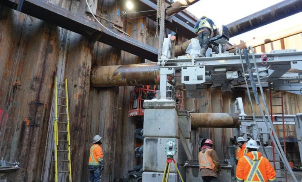
The pipes were installed in 12m-long welded segments from the portals and 6m-long segments from the shaft, using auger boring technology (Figure 5). In this method the pipes are jacked into the ground using hydraulic jacks, while soil is simultaneously being removed using an auger as a rotating cutting tool. The pipes were installed from the two portals and from each side of an intermediate shaft. Figure 6 shows photos during the installation from the portals.
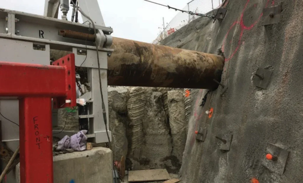
Initially, the contract required use of a closed face TBM for pre-support construction but the TTP team convinced the client’s team that use of the suggested auger boring method would provide better control of the settlements during pipe installation. Using this arrangement allowed the tunnelling team to manage settlement risks and ensure that the tunnel remained stable throughout excavation.
ADVANCED NUMERICAL MODELLING
Due to the complexity of the project and the tight settlement tolerances, the team relied heavily on advanced numerical modelling to predict ground behaviour and assess the impacts of tunnelling on nearby structures.
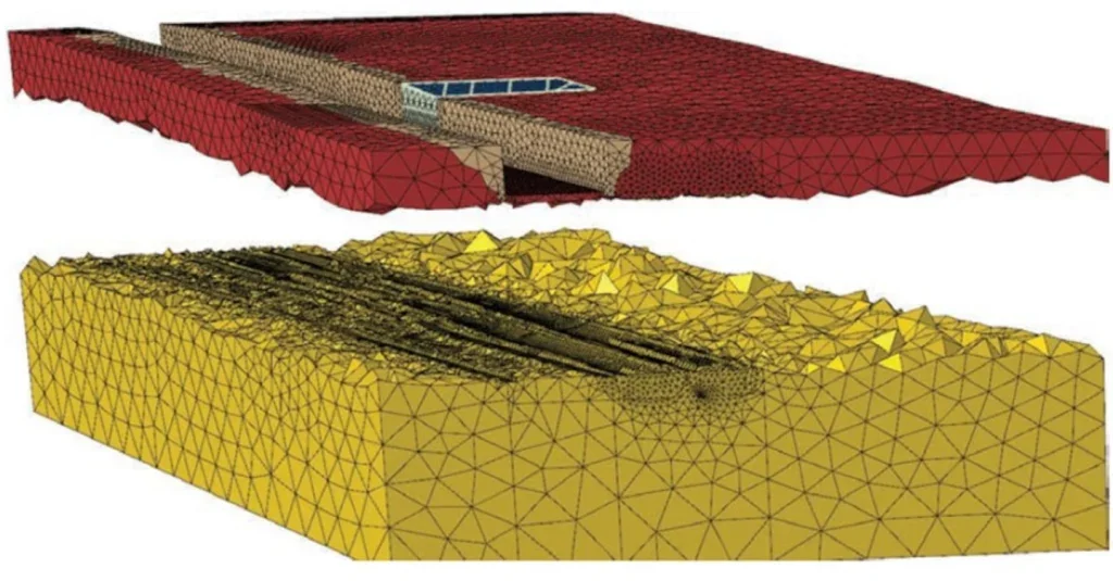
A 3D Finite Element (FE) model was developed early in the project, simulating the entire construction process, including tunnel excavation, pipe installation, and the interaction between the new tunnels and existing infrastructure.
The FE model, consisting of over 1 million elements and 459 steps, provided a detailed representation of the site’s geotechnical conditions, including the engineering fill, the glacial till deposits, and the backfill at the sides of the existing tunnel, as shown in Figure 4. Non-linear material behaviour was defined for both soil (Figure 8) and tunnel linings (Figure 7): the Hardening Mohr Coulomb model (Doherty & Muir Wood, 2013) with the main parameters shown in Table 1 was used for the soil elements; and, the non-linear Concrete Damaged Plasticity model as used for the tunnel lining. All other structural members were assumed linear elastic.
Sensitivity analyses were conducted to account for the variability in these materials, with special focus on the poor-quality backfill on the sides of the existing tunnel and the impact of K0.
Another critical aspect of the numerical analysis was the assessment of the tunnel’s fire performance. A heattransfer analysis was conducted to simulate the effects of a 1200°C fire event maintained for 120 minutes. As a result, a 60mm sacrificial layer was accounted for in the minimum thickness of the final lining.
CONSTRUCTION MONITORING AND EXECUTION
Once the design was finalised, the construction phase began under strict monitoring protocols to ensure that ground movements remained within the allowable limits. The team installed automated total stations and inclinometers to monitor both surface and subsurface settlements in real-time.
A critical part of the monitoring strategy involved observing the surface of the highway, where 21 lanes of live traffic were present.
A contract requirement was to perform a six-month baseline reading for the highway surface, the existing tunnel and the retaining walls.
Monitoring data were collected every five minutes, ensuring that even the slightest movements could be detected and analysed immediately. This approach allowed the project team to adjust tunnelling operations if necessary, preventing any disruption to traffic or damage to the highway infrastructure. In some areas, additional measures were taken, such as closing off individual lanes to minimise risk during critical phases of the excavation.
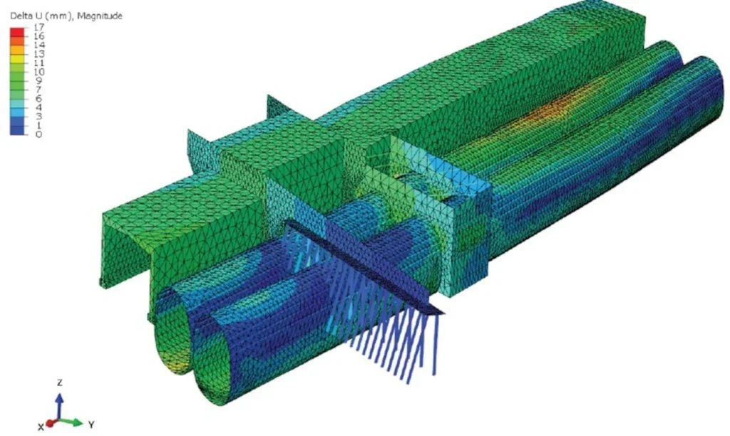
The construction activity that initially caused the largest settlements was the shaft construction in the median of the highway rather than the tunnel excavation. Also, the 800mm pipe installation was closely monitored during installation.
It was decided to excavate one tunnel at a time.. By focusing on the right-side tunnel first, which was farther away from the existing rail line tunnel, the team could closely monitor the interaction between the tunnelling operations and the nearby infrastructure. Once the first tunnel was completed, the second tunnel was excavated, ensuring that the project proceeded in a controlled and safe manner.

The chosen excavation and support sequence was a short ring closure method with top-heading/ combined bench/invert sequence, changed later to a top heading sequence with a temporary invert. Both methods worked equally well and did not show significantly different deformation patterns. Tunnel excavation was managed by the RES (required excavation and support) process, where a daily meeting between construction team, designer and client assessed the performance of the tunnel construction, surface settlement and changes to the excavation process were discussed.
Also, two cross passages were constructed along the tunnel alignment. Due to the close proximity of the two new tunnels the cross passage construction was more similar to a ‘punching-through’ exercise rather than tunnel excavation. As high waterflows during rain events were expected to occur within the highway embankment, a compartmentalised PVC waterproofing system was installed in both tunnels.
The tunnel final lining was constructed using fibrereinforced concrete, with additional reinforcement provided only at the portal areas where structural loads were higher. The lining design was informed by the results of the numerical modelling, which allowed the team to optimise the reinforcement while maintaining the required safety factors.
LESSONS LEARNT
The project provided valuable insights into the complexities of urban tunnelling, particularly in areas with very low overburden and high traffic volumes.
One of the key project lessons learned was the importance of flexibility in both design and execution. The ability to adapt the pre-support system to accommodate larger pipes and the decision to use open-face excavation methods were critical to the success of the project.
Another important lesson was the value of collaboration between the project team, client, and designers. Regular progress meetings and close communication allowed the team to refine the design as new challenges arose, ensuring that the project remained on schedule and within budget. The use of advanced numerical modelling also played a crucial role in managing risk, providing the team with the data needed to make informed decisions at each stage of the project.
Cooperation between the contractor’s site team, the designer and the owner’s team was essential for successful completion of the project. With this cooperation the project could be completed on time and budget, which was considered a great success for this project, being one of the most challenging projects executed by Metrolinx.
CONCLUSIONS
The Highway 401/409 Rail Tunnel project in Toronto represents a significant engineering accomplishment. Through a combination of innovative design, rigorous risk management, and collaborative client-contractor engagement, the project successfully navigated the complex challenges of tunnelling beneath one of North America’s busiest highway intersections.
The Design-Build-Finance (DBF) model, along with a thorough comparative assessment of design alternatives, allowed the contractor to deliver the project on time and within budget.
The lessons learned from this project, particularly in terms of settlement control, innovative tunnelling methods, and advanced monitoring, will be invaluable for future infrastructure projects in similarly constrained environments.
QUESTIONS AND ANSWERS
Following the presentation, the speakers took questions from the floor in the BTS meeting. The questions and answers are summarised below, edited for clarity and space.
Q1: Was the road settlement limit 1mm and what was the maximum actual settlement on the highway? Did the road remain open?
A1: The initial limit was set to 10mm but the design JV commented prior to the tender that this was not realistic and manged to get this limit modified. The maximum settlements were close to the retaining walls due to the vibration induced by the installation of the sheet pile walls for the shaft and were about 60mm-65mm before tunnelling commenced. A similar amount of settlement was observed in another location during the pre-support pipe installation due to an unknown obstruction. The road remained operational at all times. Even though the settlements were 60mm-65mm in local areas the slopes were very small as the troughs were rather smooth.
Q2: How was it possible to collect samples for geotechnical assessment during the tender process to provide confidence to the FE models, and how was it possible to build a shaft in the middle of an operational highway?
A2: The highway was originally a six-lane highway and then additional lanes were added. The shaft was introduced in the part between the lanes on a grass median. There were samples taken during the construction of these embankments. The confidence in the numerical models arose from the extensive sensitivity assessments. Also the soil parameters taken into the models were taken conservatively.
Q3: What are the considerations regarding the selection of mesh reinforcement for the initial lining and fibre reinforcement for the final linings, and what were the concrete parameters selected for the project? How was the simulation of shotcrete strength gain done in the numerical analysis?
A3: Mesh and lattice girders were used for the initial lining as a conservative approach as a contractor’s preference. The shotcrete was regular 35MPa shotcrete mixed on site without any particular considerations. The strength gain of the shotcrete was not simulated explicitly as a timedependent process, rather by applying a smaller Young’s modulus. There was no reason to invest more time in a complex model of the concrete as the load on the tunnels was in any case rather small due to the low cover.
Q4: What were the considerations regarding fixings onto the final lining?
A4: Fixings were installed into the final linings and were handed over to the next contracts to complete the installation of the catenaries.
Q5: Was any part of the I&M (instrumentation and monitoring) retained operational after the completion of the construction?
A5: There was a period of one year between substantial completion and final completion when monitoring was operational but then all was decommissioned.
Q6: How were the pre-support pipes monitored? Also, the pipes where shown bent downwards. Were there cases where the pipes bent upwards and affected the highway?
A6: The installation of the pipes was monitored through the centre of the auger. In the longer drives, a navigating rod was drilled-in first and then the auger boring followed. There were, luckily, no cases where the pipes bent upwards.
Q7: What was the condition of the existing tunnel prior to the start of construction? In particular, was there any deterioration due to the extreme temperature changes?
A7: The structure was from the 1960s and there were a lot of cracks, which were monitored. A very detailed monitoring system was installed to assess the impact of the tunnelling and there was no impact.
Q8: What was the actual staging of the two tunnels? Which tunnel to go first?
A8: The selection of which tunnel will start first was purely done so that the tunnel that is farther away from the existing tunnel would start first, in particular due to the weak backfill on the sides of the existing cut & cover tunnel. The only requirement from the designer was for 20m distance between the headings of the two tunnels to allow the shotcrete in the first tunnel to gain full strength. There was no requirement to install the final lining in one tunnel first. The first tunnel went through and it was almost by completion of the second when the installation of the final lining started in the first tunnel. The tunnels were 180m long each and advanced at up to about 1m/day with a long average of 50-70cm per day due to the removal of obstructions.
Q9: What was the biggest risk as encountered during construction?
A9: The pipe jacking operation was done with three machines in order to accelerate the schedule.
The biggest risk were the obstructions (boulders, wooden pieces, steel pieces) where the auger could not go through but there was a risk-budget allocated. The second was the drive through the wing-walls of the existing tunnel which was a tedious operation due to the very soft backfill.
Q10: What was the process of convincing the client?
A10: It started with the contractor’s outreach where the client realised that the concept design would not work. The client believed in the mined solution and introduced modifications to allow this solution in the tender.
During the RFP process there were a lot of people on the stakeholder side involved and it was a tedious process trying to convince and explain the particularities of the project as there were no tunnelling experts on the other side of the table who would understand the proposed method.
Q11: How were obstacles removed through a 800mm pipe?
The UK standard is 1.2m to allow personnel entering a pipe. A11: The diameter of the pipe was chosen (as opposed to 500mm) to allow removal of the auger and allowing a person to enter the pipe providing necessary light, ventilation and quick escape means and this person was manually removing the obstacles.
REFERENCES
- Doherty, J. P. & Muir Wood, D. (2013). ‘An extended Mohr-Coulomb (EMC) model for predicting the settlement of shallow foundations on sand.’ Geotechnique, 63:661–673.
- Ferraro, M.J., & Lahti, T. (2021). ‘Tunneling under highway 401: Construction of a large diameter pre-support pipe canopy.’ TAC Conference, Vision Underground.
- Urschitz, G.J. (2019). ‘At the Limit–Soft-ground tunnelling under the city highway of Toronto.’ Geomechanics and Tunnelling, 12(5), pp.440- 449


