Soon, four TBMs will arrive at two giant shafts at Greenford, in west London, to finish their drives to build twin-tube tunnels for the HS2 rail project. The shafts awaiting them at the Greenpark Way site have been sunk 45m into the ground in a former landfill site, which before that was a munitions factory. They are also near a surface rail line. Groundwater in the area is high, adding further to the challenge of building the shafts but also for receiving the TBMs.
The TBMs are excavating the 13.5km-long Northolt Tunnel, in west London, with works split in two sections – Northolt Tunnel West and Northolt Tunnel East, respectively. Where the sections meet is the location of the shafts that will be their extraction points, each individual shaft taking two TBMs closing from opposite directions. Also, in future, the shafts will form ventilation outlets, with a headhouse, for the high-speed rail tunnel.
MEETING POINT – CHALLENGE
The TBMs have been driving in pairs, coming in from the west and east to close-in on the shafts at Greenford. The sections to the west and east of Greenford, respectively, are 8km-long Northolt Tunnel West and 5.5km-long Northolt Tunnel East.
For the Northolt Tunnel West section, two of the TBMs were launched on parallel drives from the farthest west point on the entire tunnel, at West Ruislip; the other two machines were launched from the site farthest east, at the Victoria Road Crossover box, in North Acton.
While tunnel boring always has its own challenges so also does construction of shafts, and Greenford is no different – and perhaps moreso, for it has large diameters, limited space and a tight timeline to be ready to receive the TBMs.
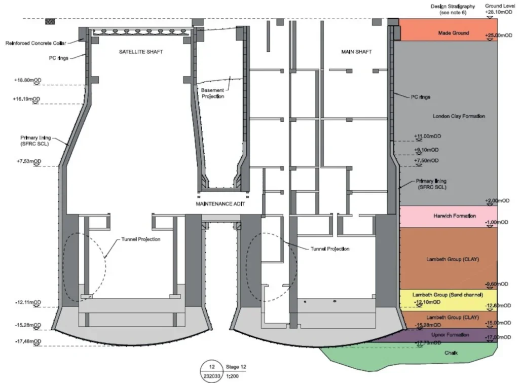
The ground profile at the shafts’ location is, in sequence, from the surface – made ground over London Clay of 21m thickness, above 3m of Harwich Formation, then Lambeth Group (clay, sand), Upnor Formation, and Chalk below. Pore pressures are up to 450kPa at the bottom of the shafts.
Consequently, with such groundwater, when TBMs break into shafts there would be a lot of inflow coming along with them, normally. The challenge on this part of the HS2 construction project is preventing that in preparations for the coming breakthroughs of the large machines. A large-scale engineering solution was needed to ensure sealing and stability.
Skanska Costain Strabag Joint Venture (SCS JV) is contractor for HS2’s Northolt Tunnel project and is using a novel technique to overcome the challenges – in time for the first TBM to arrive, later this year.
MEETING POINT – SOLUTION CONCEPT
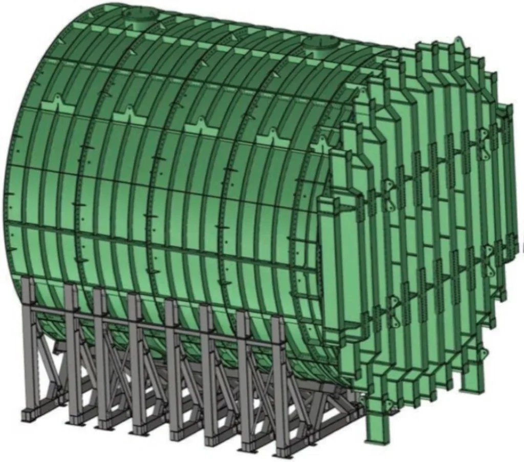
Standard practice is for a TBM to break straight through into an open shaft. Here, with the groundwater difficulty though, the principle is to use a large, sealed steel ‘can’ to receive one TBM at a time.
Such a ‘can’ would be set horizontally across the floor of the shaft, as if laying on its side. At the ends, the ‘can’ would be secured into steel ‘shutter pipe’ structures, themselves built into the shaft head walls with sealed ‘eye’ openings through which TBMs will eventually pass. The entire steel assembly holds back groundwater.
The process steps of the concept is for an arriving TBM – having built a watertight segmentally-lined tunnel behind it – enter into the awaiting sealed horizontal ‘can’. At the opposite end is a steel bulkhead ‘lid’, closing off the ‘can’.
Before the TBM comes into the ‘can’, the gap between the structures is ensured sealed. Then, once the TBM is in the ‘can’, the top side of the structure can be opened; the TBM is lifted out. The ‘can’ is then restored and can be used again for the next TBM extraction.
Each shaft sits on the line of a running tunnel. Therefore, a shaft can use a ‘can’ to take out two TBMs, coming from opposite directions; it would do so by the ‘can’ later being turned around in the shaft and readied to receive the other machine. Of course, the ‘can’ will need cleaned and prepared for the second reception task, in each shaft.
MEETING POINT – ENGINEERING THE SOLUTION Shafts
Work has been underway over the last few years to prepare the site and shafts to receive the four TBMs at the end of their drives. Site set-up for the two shafts began in 2020; Schedule 17 planning approval came in June 2021. The shafts – a main ventilation shaft and a satellite shaft, respectively – are now fully built.
The main ventilation shaft is 20m-diameter and cylindrical. The satellite shaft, beside it, is cylindrical from halfway down; above that level it narrows, asymmetrically, reducing from the lower diameter of 19.45m to 15m at the top. The adjustment was necessary to accommodate being near to National Rail tracks, which run just 2.7m from the offset lip of the shaft.
The same water issues that complicate TBM extraction also made construction of the shafts themselves challenging. One danger was the likelihood of uplift of the impermeable clay layers from the groundwater pressure in the chalk beneath. Depressuring the chalk and dewatering were necessary until the installation of the full secondary linings of the shafts, which provided sufficient weight to counteract the upward pressure.
Chris Hewett is Sub Agent at SCS JV. “We used a twostage process,” he says. “Grout columns were used in a figure-of-eight shape around the footprint of the shafts to reduce inflows of water, with jet grouting into the upper formations; then we drilled dewatering wells.”
The initial plan was for 32 wells, all actively pumped. More wells were progressively found to be needed. One reason is that fissures in the chalk could not be mapped ahead of the excavation.
“We had to dig 136 wells altogether. Some of them are actively pumped, others are flowing ones to relieve pressure in the chalk. At the beginning we had inflows of 110 litres of water per second; after the remedial measures this went down to 30 litres/second.”
The water was disposed of in drainage wells, sunk within the site but far enough from the excavation not immediately to seep back to it.
“That way, we would be replenishing the aquifer,” says Hewett.
Secondary linings, of concrete segments and sprayed concrete linings (SCL), were installed in both shafts.
Adam Barratt, Costain Group’s Senior General Foreman on site, says, “We had to use bog-mats for the excavators at the bottom, or we would have lost some big machines.”
The ‘can’
So far so good: stable watertight shafts have been established.
Next, the watertight breakthrough solution adopted for the large TBMs is a first, certainly for the UK.
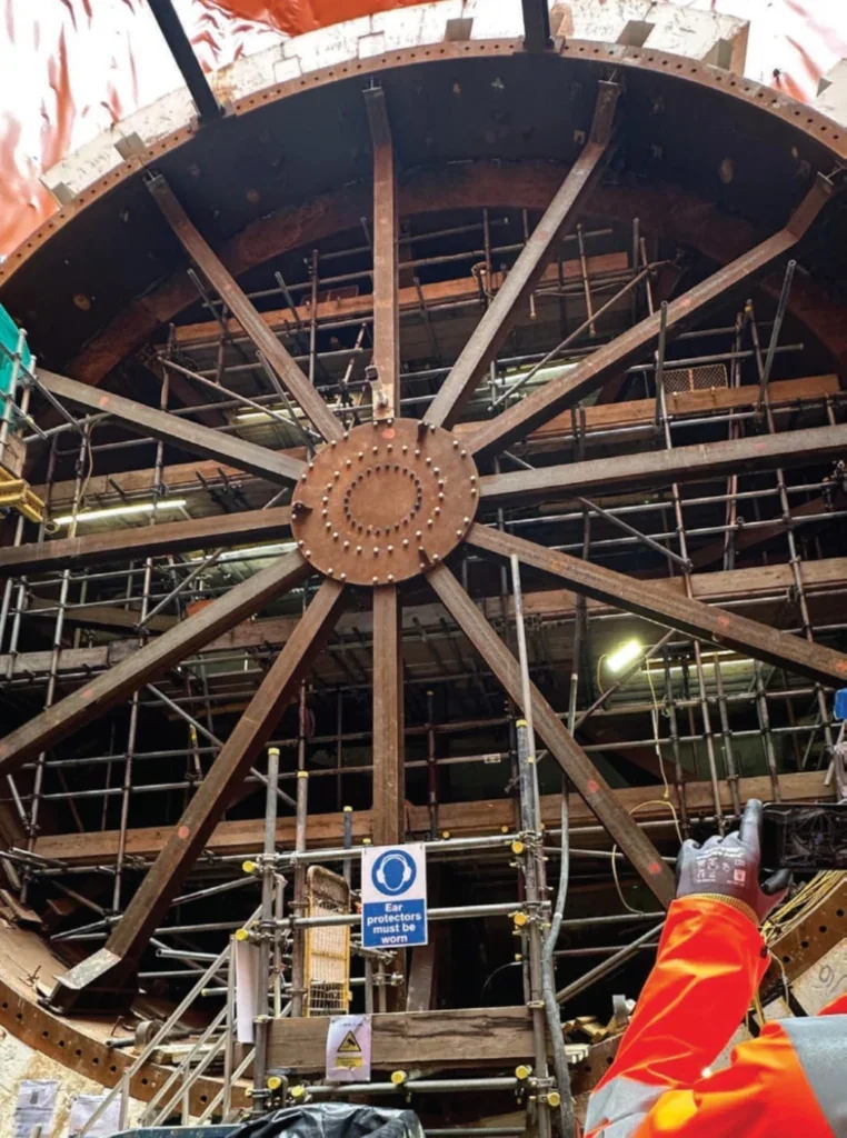
The hollow steel ‘can’ is to be erected in the shaft by installing in sections, bolted together. The ‘can’ will rest on a cradle. A specially-shaped ‘shutter pipe’ is at each end, joining it snugly to the shaft walls.
A steel ‘lid’ will be fixed to one end of the horizontal ‘can’ – the end farthest from the approaching TBM. The lid weighs 78 tonnes, is in three sections, and held in place by jacks.
The ‘can’ is to be filled with some suitable substance – foam concrete fill is the current proposal, yet to be confirmed. The TBM will excavate into the fill, and send the resulting muck back through the tunnel as it does so. Water coming in with the TBM will be contained in the ‘can’ and not leak into the shaft; the annular gap between the shaft and the tunnel will be sealed.
The end result is a tunnel with watertight walls, joined with a watertight seal to the watertight vertical shaft. When the seals have been checked and any water pressure released, the top half of the ‘can’ is able to be opened, to reveal the TBM within. Cranes will then lift the TBM out of the shaft; as normal practice, it will come up in sections to the surface.
“The TBMs could be lifted out by the cranes we have on site,” says Barratt. “But we are considering installing a gantry crane for the job; that would shorten the extraction time from 90 days down to 30, which would be a big saving.”
To accommodate the second TBM to arrive at a shaft – approaching from the opposite direction after a suitably-planned time interval – the ‘can’ is raised, section by section, cleaned, and if necessary the interior surfaces sandblasted should there have been deterioration from the entry of the first TBM. Then, the steel sections are lowered down the shaft again and the ‘can’ is reassembled, to be made ready to receive the second TBM.
With the machine coming from the other direction, this time the ‘lid’ would be positioned at the opposite end of the ‘can’. All else is basically the same.
Except for one small difference, in that the pairs of TBMs are of different diameters. The reason is due to the operational use of the HS2 tunnels – more precisely, the speed of trains at different sections.
Hewett says, “Trains from the London direction will not yet have accelerated to full speed; the space needed for air to pass by – the so-called ‘piston effect’ – is therefore slightly less. A faster train needs a wider tunnel to let the air get past it.”