Mexico’s largest infrastructure project is a 62km long emergency wastewater pipeline being built to prevent flooding in the downtown area of the capital. Ground settlement in Mexico City has caused the existing gravity feed wastewater system, built in 1975, to lose its Slope. Much of the main pipeline, Emisor Central, is severely corroded and at high risk of failure, which would cause up to 5m of wastewater to flow into Mexico City’s surface streets.
To remedy the problems, the Mexico National Water Commission (Conagua) released a contract for a 7m internal diameter, long pipeline known as the Emisor Oriente Wastewater Tunnel. To meet the demanding schedule, six 8.93m diameter EPBMs were required.
Mexico City, a metropolis of more than 22 million people, is sinking at the rate of 100mm per year. The world’s second largest city was founded by the Aztecs in the Valley of Mexico, on what was once an island in the middle of Lake Texcoco. Spanish conquistadores later drained the lakebed using a system of canals, but the soft lake clays remained underneath the city’s infrastructure. A combination of a booming population and compression on the city’s main sewer lines has necessitated the creation of the Emisor Oriente tunnel.
Mexico City’s wastewater system is almost exclusively served by the Emisor Central, a 68km-long line built in 1975, which has lost capacity over the past three and a half decades, as ground settlement caused a decrease in slope in the gravity sewer line. Severe corrosion and nearly continuous groundwater infiltration also made it impossible for the Emisor Central to be inspected and maintained between 1995 and 2008.
Once inspection was made possible, it was found that the overall system capacity had been reduced by 40 per cent since 1975—from 280m3/sec to 165m3/sec in 2008. Over the same time period the city’s population more than doubled from 10 million to more than 20 million inhabitants, increasing demand on the system.
Despite its obvious need, the project is not without some controversy, particularly for the valley’s farmers. Mexico’s untreated wastewater flows through a system of open canals that feed much of its farmland. The lush bounty of crops is the direct result of fertilisation by the so-called ‘black waters’, which will be stopped by the commissioning of the new Emisor Oriente line and wastewater treatment plant.
Project description and location
Conagua recommended immediate construction of a new line to help supplement the struggling system (see Figure 1, right). The Emisor Oriente will increase the city’s current sewer capacity by 150m3/sec once complete and will carry wastewater from Mexico City to several water treatment plants currently under construction in the state of Hidalgo.
The construction of the line was divided into six lots (see Figure 2, right)—lots one, two and five under Mexican contractor Ingenieros Civiles Asociados (ICA), and lots three and four under Carso Infraestructura y Construccion. Lot six is being constructed by Lombardo Construcciones and Constructora Estrella. All six lots will be bored by EPBM. Robbins was chosen to supply lots three, four and five, which will all be bored using three EPBMs.
Geological conditions
Original conditions
Original geology was based on multiple borehole tests conducted along the tunnel length. The geology of the Valley of Mexico is highly complex, with large boulders up to 600mm in diameter predicted throughout the drives. This particular set of geologic characteristics is found only in Mexico and in certain areas of Japan.
Actual geologic conditions
Despite rigorous testing, excavation of the shafts in 2009 and 2010 revealed much more difficult geology than originally anticipated (see Figure 2, page 24). These changes in geology resulted in some modifications to the designs of the machines, depending on the ground conditions in each lot. Lots three and four were found to include abrasive basalt, volcanic rock and higher water pressure.
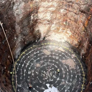
Shaft excavation
The project includes the construction of 24 shafts starting from 23m and going to 150m deep. Shafts five, 10, 13, 17 and 20 have the diameter of 16m, while the rest are 12m in diameter.
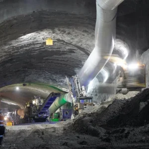
The shafts were constructed by using three main methods: slurry walls, traditional excavation and hydraulic hydro roadheader for the most difficult geology. Many of the shafts were constructed by both methods—using the slurry wall up to a certain depth and after that the traditional method.
With the exception of shafts constructed by the hydro roadheader, the slurry wall could only be constructed up to 46m, since it was limited by the capacity of the guided clamp. Shafts deeper than this had to be cut by the traditional method after 46m.
The traditional method consists of excavating 1.5m, then installing steel rebar mesh, ring beam and shotcrete. After each level is secured another 1.5m excavation can start.
After the primary lining is finished, a secondary lining is installed by using a sliding form. This secondary lining gives the shaft more structural rigidity.
Machine design
The three EPBMs supplied by Robbins are 8.93m in diameter. All of the machines are designed for the mixed ground conditions.
Cutterhead design
The machines are using mixed ground, back-loading cutterheads for the variable geology. The design allows for a change in cutting tools between sections of soft ground and rock.
The seven-piece, spoke-type cutterheads consist of six outer segments plus a hexagonal-shaped centre section to maximise the opening ratio of the face. The machines were designed with the largest possible opening ratios to ensure a smooth flow of muck into the cutterhead chamber.
Crews can switch out between high pressure, carbide knife-edge bits and 17in carbide disc cutters depending on the ground conditions. A number of small shafts, spaced every 3km between the larger launch shafts, will be used to perform cutter inspection and changes. Specialised wear detection bits will lose pressure at specified wear points to notify crews a cutting tool change is needed. The knife edge bits are arranged at several different heights to allow for effective excavation at various levels of wear.
The design also allows for bearing and seal removal from either the front or back of the cutterhead. There are 25 injection ports spaced around the periphery of the machine that can be used for injection of various additives depending on ground conditions, and for probe drilling.
Screw conveyor and muck removal
Each machine is fitted with a ribbon-type screw conveyor 900mm in diameter. The screw conveyors allow boulders up to two-thirds the screw diameter (up to 600mm) to travel up the shaft, where they are disposed of through a boulder collecting gate. Each of the three machines may encounter pressures of up to six bar, necessitating a two-screw setup with a ribbon screw and shaft-type screw in order to smoothly regulate pressure.
Muck is deposited from the screw to a rubber belt conveyor mounted on the trailing gear, which transfers to a sidemounted continuous conveyor. The continuous conveyor carries the muck to a 150m long vertical belt conveyor located at the launch shaft.
Once at the surface, a radial stacker deposits muck in a kidney-shaped pile for temporary storage. This system will be used on all three lots.
The three continuous conveyor systems, also provided by Robbins, consist of 762mm wide fabric belt at a 3,200m length and 900 tonnes per hour capacity. Approximately 22 per cent of the conveyor systems will be travelling through curves, with a minimum 700m curve radius. To better handle curves, the systems will use self-adjusting curve idlers. These idlers pivot to accommodate changing load tensions around curves. The pivoting action is favourable because it does not unnecessarily alter the carrying capacity of the conveyor or the belt tension.
Articulation
For accurate tunnelling through curves, each machine features active articulation. Active articulation engages articulation cylinders between the front and rear shields to steer the machine independently of the thrust cylinders. The process allows the thrust cylinders to react evenly against all sides of the segment ring during a TBM stroke in a curve. Typical configurations, which use flat joints to articulate the shield, are capable of making two to three degree curve adjustments over the length of the segment or stroke.
Another reason active articulation was chosen for this project was the risk of segment deformation, or cracking. A common cause of project delays, deformation occurs most commonly when the passive articulation system is used in curves. Passive articulation does not use articulation cylinders independent of the machine’s thrust cylinders, so the TBM reacts against sides of the segments unevenly in curves.
Modifications to the machine design
Several modifications were made to the machines to accommodate the longer sections of hard, abrasive rock coupled with high water pressures that were discovered during shaft construction.
These modifications include:
• A two-person man lock added to all of the machines, capable of withstanding the higher pressures. With abrasive ground, more frequent cutter changes are anticipated.
• All machines were outfitted with a redesigned pressure bulkhead for high water pressure.
• Hard facing added to each turn of the screw conveyor and the conveyor casing on the lot three TBM, in order to withstand abrasive hard rock.
• Hydraulically operated boulder collecting gates replaced manual gates on the machines, to make removal of numerous boulders more efficient.
• A high-pressure bentonite injection system added to the lot four machine for ground conditioning.
Concrete tunnel lining
The tunnels are being fully lined with concrete segments. After an excavation cycle of the TBM, a concrete segment ring is assembled at the tail shield of the EPBM. The primary lining consists of universal concrete rings designed as having seven segments plus a key.
Each ring has the following dimensions:
• Outer diameter: 8.6m
• Inner diameter: 7.8m
• Thickness: 0.4m
• Length: 1.5m (conical)
Each segment ring is designed to receive the thrust cylinders of the TBM evenly during a push.
The segment design also includes ports for the pickup system of the segment hoist on the TBM; these same ports can be used for secondary grouting through the segments if necessary.
Reinforcement of each concrete segment is made out of rebar, which is designed to resist the varying earth pressures on the tunnel alignment. For deeper tunnel sections the rebar has been designed as a very close-knit pattern.
Segment plants
To be able to guarantee the supply of the segments, two segment ring plants were built, along with one plant that was already working. The production is set at 567 segments a day, equivalent to 81 complete segment rings, to be able to comply with the demand of six TBMs operating at once.
During the course of tunnelling each plant will fabricate 14,000 segment rings, and will use 120 workers daily. Each segment requires six to eight hours to complete. The total lining of the 62km-long tunnel will require a total of 42,000 complete segment rings.
Secondary lining
A secondary lining will be installed after finishing each drive of the tunnel. The concrete will have a thickness of 250mm. The secondary lining will be installed by means of a telescopic continuous casting form, in order to avoid joints in the concrete lining.
Current site 2011 operations
As of October, the first of the EPBMs originally destined for lot four had been fast-tracked for launch at the lot one site. The critical lot one site, located in the Ecatepec area outside of downtown Mexico City, has seen widespread flooding during each rainy season—a predicament that delayed the launch of a different machine at the site for six months. In order to compensate for time lost, lot one contractor ICA began boring a 5km section from the opposite direction using a different manufacture of machine.
A pumping station is currently being built at the severely affected lot one site, which will go into service before the rest of the wastewater line is complete. The finished lot one section will then be sealed off to allow the excavation to continue. The water will be diverted into the Emisor Oriente, then pumped downstream into a part of the Gran Canal less affected by loss of slope and erosion.
The machine has to date bored about 279 rings, or 418m, in very soft and clayey geology. No boulders, sand or other abrasive material have yet been encountered on the drive.
The lot three machine being assembled at shaft 10 is about 50 per cent complete with its assembly. Back-up gantries have been assembled at the surface, and lowering of the newly redesigned machine components including the man lock and bulkhead is proceeding as planned.
Launch of the lot three machine is scheduled for this month, with assembly of the lot five machine in January 2012.
The 62km long wastewater tunnel project features 23 shafts up to 150m deep Figure 1, Mexico City’s Emisor Oriente Pipeline stretches 62km Figure 2, the revised geology at Emisor Oriente includes longer sections of abrasive basalt and volcanic rock Table 1: Specifications for Emisor Oriente EPBMs Rebar reinforcements for the tunnel’s concrete segments are designed to resist varying earth pressures