


M. Alonso1, J. Vaunat1, M-N. Vu2, J. Talandier2, S. Olivella1 & A. Gens1 1Department of Civil and Environmental Engineering, Universitat Politècnica de Catalunya, Barcelona, Spain 2French National Radioactive Waste Management Agency (Andra), Paris, France
INTRODUCTION
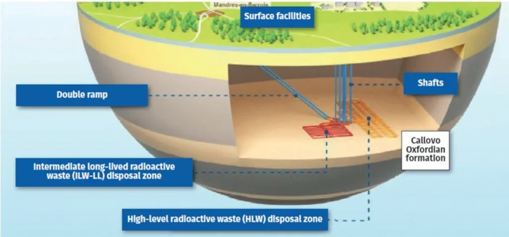
The French National Radioactive Waste Management Agency (Andra) is leading the design of a deep geological radioactive waste disposal to be located in the Callovo-Oxfordian formation. At the disposal main level of the proposed Cigéo repository, large-diameter galleries are to provide access to storage cells and connection between zones. After a long operational period, the disposal facility is to be closed by large diameter sealing structures, intended to prevent the flow of water and the migration of radionuclides over the post-closure period (~ a few thousand years).
The paper presents the assessment and simulation of the phenomena underlying the response and performance of the sealing concept under real disposal conditions, looking at: 3D hydro-mechanical modelling of sealing off the galleries in clayey rock; the large geometries involved, plus interfaces and anisotropy; progressive hydration and swelling of the sealing core; longitudinal movement of concrete plugs while core density and swelling pressure do not significantly change; and, the swelling core resulting in some recompression of the excavation-induced damaged zone (EDZ) in the area of lining deposition.
PROJECT
Due to its very low hydraulic conductivity, low effective diffusion, and significant radionuclide retention capacity, the Callovo-Oxfordian (COx) claystone is being considered to act as the host formation for geological disposal of radioactive waste. Andra is leading the design of Cigéo, a deep geological disposal to be implemented (if authorised) in eastern France at about 500m depth, in the Cox claystone (see Figure. 1).
The main role of a deep geological disposal is to isolate the radioactive waste from humans and biosphere. The long-term safety of such facilities is associated with their ability to protect the environment over the period of several millions of years (Gens 2004).
The long-term safety of Cigéo relies on the COx claystone and the so-called sealing structures, positioned in key positions in shafts, ramps and horizontal drifts. They are intended to limit the flow of water and the migration of radionuclides.
Excavation of underground drifts leads to significant changes in the local stress field and generally causes damage to the rock around the openings. The area affected around the drifts is generally identified as the EDZ and the alterations usually imply significant changes in flow and transport properties (Blümling et al. 2007).
Since water is one of the main transfer vectors of radioactive substances, controlling the preferential pathway of groundwater through the fractures caused by excavation is a key objective. The sealing structures should be therefore designed not only to seal the drifts but also to reduce the EDZ to low permeability, recreating conditions similar to those of the intact host rock.
Performance assessment to confirm the design of the sealing structures and to verify that requirements are fulfilled is complex, given the variety of materials and the large number of interacting processes and phenomena to evaluate, and the extremely long periods of time under consideration (Gens et al. 2021).
Numerical simulation is a useful and powerful tool to better understand the behaviour of the engineered barriers. The paper presents the work carried out to assess and simulate the phenomena underlying the response and performance of the large-diameter sealing concept under real disposal conditions.
SEALING STRUCTURE:
CURRENT CONCEPT OVERVIEW
In the Cigéo concept, large-diameter galleries (~10m excavation diameter) would provide access to the storage cells and connection between different parts of the deep disposal facility. Sealing these tunnels is challenging. Due to its high swelling capacity when hydrated with water and its low permeability, bentonite is a potential sealing material in several sealing systems designs (Sellin and Leupin 2013).
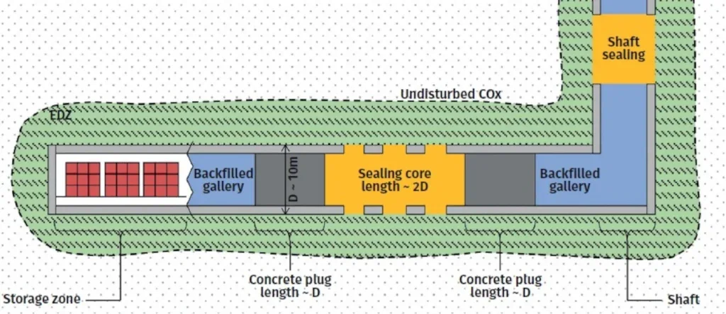
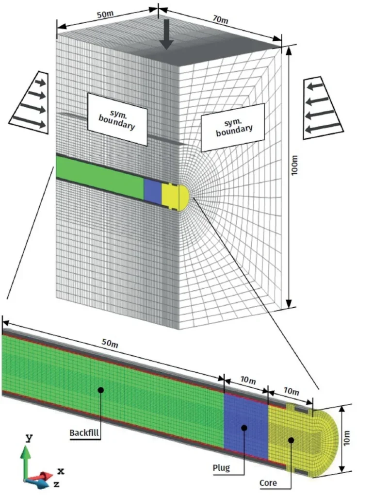
Andra’s current sealing concept is for a confined expansive bentonite-based sealing core, occupying the entire cross-section area of the drift (see Figure. 2). The expansive core would be confined by two concrete plugs, one at either end. The remaining portion of the drift would be backfilled with disaggregated and recompacted excavated COx claystone.
Swelling under confined conditions leads to the development of a swelling pressure that the core exerts on the surrounding materials. In this way, as the EDZ is re-saturated it will be gradually compressed by the progressive long-term deformation of rock and the increasing pressure exerted by the expansive core. This will lead to a gradual closure of the fractures, favouring self-sealing, and leading to a gradual recovery of the rock’s low permeability (Bastiaens et al 2007; De La Vaissière 2015; Wang et al 2022a, b).
The performance of this type of solution, therefore, relies on the development and long-term stability of the core swelling pressure and the recompression of the EDZ. The retaining plugs and the backfill material must provide the support necessary, so that the deformation at the ends of the core are limited and the swelling pressure remains within the target design range.
There are several configurations of concrete retaining plugs under examination (i.e., lengths, anchoring methods). In this study, the plugs are assumed to be constructed inside the lining but without any anchoring system, and their length is assumed to be equal to about one diameter of the drift (~ 10m). On the other hand, the core length is designed to have a margin of safety against a possible deconfinement and reduction of swelling properties and increase of permeability at the ends of the core. In this case, core length is assumed equal to twice the excavated diameter (~ 20m).
The design of the bentonite-based material for the core requires necessary low permeability and appropriate swelling potential. The placement method must minimise residual voids and ensure the most uniform core properties. This paper considers bentonite powder–pellets mixtures as the preferred option, with operational advantages including facilitating underground placement of large quantities to target density.
For the numerical simulation, it is important to identify and understand all the processes and phenomena involved behind the response of the sealing structures that may affect their performance. At this stage, the uncertainties related principally to: how the self-sealing contribution should be considered in performance assessments; and, how sealing structures will be able to reproduce, by means of swelling pressure, the mechanical effect that helps to restore low permeability of the COx claystone. This paper looks at the latter aspect.
The sealing structure is intended to be placed relatively far from the storage zone and, therefore, from heat sources. For this reason, isothermal conditions are assumed and long-term effects of temperature are not considered. Physico-chemical processes between bentonite and the nearby materials, and gas pressurisation due to degradation and corrosion of the support elements, are not considered.
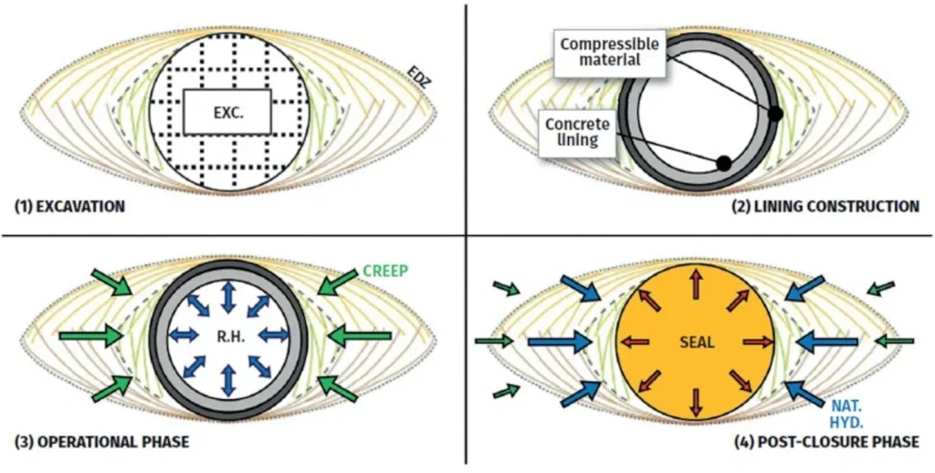
Under these considerations, there are four main phases in the life of a gallery and its sealing, shown in Figure. 3 and summarised as follows:
- Phase 1 – excavation procedure, creating the EDZ;
- Phase 2 – excavation lining. Consists of two layers: primary lining (50cm thickness) is concrete; secondary (20cm) is compressible, made from reformed COx claystone.
- Phase 3 – facility operation for 100 years. Galleries are open access tunnels. Must consider interaction of the COx claystone and the relative humidity caused by tunnel ventilation. Interaction between the compressible secondary lining and the host rock also plays an important role, due to long-term behaviour associated with rock creep deformations and hydromechanical evolution towards equilibrium.
- Phase 4 – post-closure, when the most important phenomena take place (see Figure. 4).
Before seal construction, the draft lining will be partially removed, by portions, over the length of the core, to ensure direct contact between the expansive core and the host rock at certain points.
During the post-closure phase, water seeps from the host rock towards the sealing core. The core begins to swell, exerting pressure on the host rock and concrete plugs, which slide and compress the drift backfill, releasing some of the swelling pressure in the core. Equilibrium is reached when the expansive core pressure (longitudinal, parallel to the drift) is countered by the stabilising forces. Sealing performance is strongly related to the stability of the entire structure.
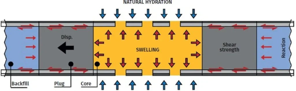
In this type of sealing configuration, equilibrium basically relies on shear strengths at the following interfaces: between the plugs and the lining (i.e., concrete–concrete interface); between the backfill and the lining (i.e., clay–concrete interface); and, on the strength and stiffness of the backfill itself reacting to compression.
Here, the performance of the sealing structure as a whole is evaluated by considering the individual performance associate with capability of the sealing core to reach full saturation at all points; develop the target swelling pressure as uniformly as possible; and, recompress the EDZ. Also, the stabilising components (plugs and backfill) must provide long-term stability to the swelling core and maintain the swelling pressure.
NUMERICAL SIMULATION
Basic Theoretical Formulation
Simulations were carried out with the software CODE_BRIGHT, a finite-element code designed to model coupled thermo-hydro-mechanical processes in porous media (Olivella et al. 1994). The basic theoretical formulation consists of governing equations based on mass and momentum conservation principles, completed by constitutive laws and equilibrium constraints.
For the sake of simplicity, a particular case of the general formulation is considered. The porous medium is assumed to be composed of a solid (s) phase (composed only of minerals), a liquid (l) phase (composed only of water), and a gas (g) phase (composed only of dry air). Moreover, gas phase is assumed perfectly mobile, and therefore, gas pressure (Pg) remains constant during all the analysis.
Under these considerations, the relevant balance equations are the balance of solid mass and water mass, respectively, and total stress equilibrium. Analysis involves the simultaneous solution of stress equilibrium and water mass balance equations. The main unknowns, usually called independent or state variables, are the displacements and the liquid pressure linked to the dependent variables (solid and liquid densities, saturation degree, and total stress tensor) through a set of constitutive laws, some being generic to all materials.
Details about the hydro-mechanical constitutive model considered for each material are given in the following sections.
Geometry and Main Features of the Numerical Model
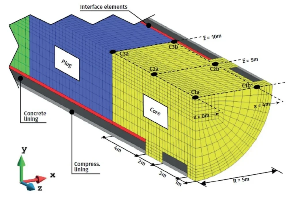
Model dimensions and the finite-element mesh are illustrated in Figure. 5. Details of the model around the sealing core can be seen in Figure. 6, where, for ease of viewing, the upper half of the model is hidden. This figure also shows the position of six points within the core used as results’ output points. The mesh is constituted by 8-node hexahedral linear elements (total amount of almost 150,000 elements and 160,000 nodes). Each node has four degrees of freedom or unknowns (displacements in the three spatial directions and liquid pressure).
Advantage was taken of two planes of symmetry (“x–y” and “y–z”, labelled “sym. boundary” in Figure. 5) to analyse only a quarter of the full problem domain. Null displacement and null flux of water were prescribed on these planes during the entire simulation. Since gravity effects are considered, it is not possible to take advantage of a third plane of symmetry.
For the initial stress state of the COx claystone, the anisotropic in-situ state estimated by Wileveau et al. (2007) was considered. At the main disposal level, the major principal stress is horizontal and aligned with the drift (σH ≈ 15.6 MPa). On the other hand, the vertical (σv) and the minor horizontal (σh) stresses are close to each other (σv ≈ σh ≈ 12 MPa). To account for gravity, a linear variation with depth of the three stress components was prescribed as initial values in the model, setting the previously mentioned values at the depth of gallery centreline. For the initial water pressure, a hydrostatic distribution was considered with a value of 4.7 MPa, set at the gallery centreline (Armand et al. 2013).
Regarding the sealing materials (core, plug, backfill), the initial stress state is given by the selfweight of the components. Initial saturation degrees were assumed for the expansive core (≈ 0.35), the concrete plugs (≈ 0.80), and the backfill (≈ 0.70), respectively.
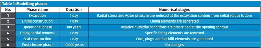
All the phases described in Figure. 3 were simulated. Table 1 summarises the numerical features related to the processes involved in these phases. It is assumed that the excavation, lining construction, lining partial removal, and seal construction phases are almost instantaneous in comparison to the other phases. For this reason, a duration of 1 day is adopted for each of them. Postclosure phase is simulated up to maximum of 10,000 years.
In Figure. 6, ‘interface elements’ are located between the concrete lining and the seal components (core, plugs, and backfill). They are 8-node hexahedral linear elements and transmit the normal and shear stress from one medium to other. They are provided by a Mohr–Coulomb based constitutive model, which limits the maximum shear stress according to the applied normal stress. The stress–strain response is quasirigid- perfectly plastic. Only frictional shear strength is considered and dilatancy is neglected.
A value of interface friction angle of 10° was adopted for both the core-lining interface and the backfill- lining interface, which can be associated with the residual strength of the clay that constitutes these components. For the plug-lining interface, a typical value for concrete–concrete contact of 30° was initially adopted. The effect of the plug-lining interface strength on seal performance was subsequently studied by varying.
Constitutive Model for the Host Rock
The modelling of the failure process and EDZ creation, and specially the consequent increase of permeability, requires the selection of an adequate constitutive model. It must be capable of simulating the most important features of COx claystone behaviour, such as strength anisotropy, brittle failure, strain softening, timedependent deformation, and permeability variations.
The model adopted was specifically developed for the COx claystone, as described in Mánica et al. (2017). It is outlined here.
It is important to note that the model was developed in a local form (i.e., the history variable employed in the hardening/softening law is the one computed at the current integration point).
This aspect of the model does not allow regularising the problem of strain localisation associated with softening. Further work using a non-local model as a regularisation technique has been presented by Mánica et al. (2022), for 2D applications.
But the huge computational resources required by these techniques in large 3D geometries make its application currently impracticable for the problem under consideration. For this reason, the local model presented by Mánica et al. (2017) is employed at this stage. Considerations about the representativeness of the solution obtained using this model are discussed.
The model assumes that the total strain increment can be decomposed into elastic, plastic and creep strain increments. The first two are described within the framework of elasto-plasticity, and for the latter there is an additional time-dependent element employed.
The Mohr–Coulomb criterion is adopted for both yield and failure limits. Strain–stress relation is given by a generalised cross-anisotropic Hooke’s law type (with five independent elastic parameters). Strength anisotropy is included through a non-uniform scaling of the stress tensor (Manica et al. 2016).
After reaching the yield limit, an isotropic non-linear hardening/softening mechanism is considered. The evolution of strength parameters is controlled by the equivalent plastic strain.
Friction angle varies in a piecewise manner. Cohesion varies in parallel with the friction angle. Creep strain rates are higher at higher deviatoric stresses, and decrease as creep strains accumulate over time.
Finally, the increase of permeability with irreversible strains is incorporated into the model by including a dependency of the intrinsic permeability on the equivalent plastic strain.
The model was validated by reproducing and comparing results of triaxial and creep laboratory tests on COx claystone (Manica et al. 2017). It has also been shown to reproduce, in the context of a Transverse Action benchmark programme, the extension and shape of the EDZ in a 5m-diameter drift in the Meuse/ Haute- Marne Underground Research Laboratory (MHM- URL) at Bure (Seyedi et al. 2017).
For the simulations presented in this paper, the host rock parameters have been completed by parameters obtained from more recent laboratory and field data.
Constitutive Model for the Expansive Core
The bentonite powder–pellets mixture is the current preferred material for the sealing core. The technical feasibility of implementing powder–pellets mixtures at large scale has been assessed in the framework of the European DOPAS project with the FSS experiment (Bosgiraud et al. 2015; Noiret et al. 2016). A mixture of 70% bentonite pellets and 30% bentonite powder was successfully installed with an average dry density of around 1500 kg.m-3 (reference value for the described case).
Gens and Alonso (1992) presented the conceptual bases to model expansive soils, further implemented by Alonso et al. (1999) in the Barcelona Expansive Model (BExM) which has been successfully employed to simulate bentonite powder–pellets mixtures. It is adopted for the core material (Gens et al. 2011; Ruiz 2020).
Two structure levels are distinguished in the BExM: the microstructural level, at which swelling of active minerals takes place; and, the macrostructural level, responsible for major structural rearrangements. The coupling between these levels is accomplished through a strain coupling mechanism that accounts for the macrostructural strains that arise from the deformations that occur at microstructural level.
Microstructural behaviour is assumed elastic and volumetric. On the other hand, macrostructural behaviour is simulated through the Barcelona Basic Model (BBM) developed by Alonso et al. (1990). The stress–strain relationships of the BBM model are established in an elasto-plastic framework.
The key element of the BBM is the Loading-Collapse (LC) mechanism given by the dependency of the yield locus on suction.
The direction of macrostructural plastic deformations that develop is governed by the plastic flow rule. It is assumed that microstructural swelling and shrinkage affect the structural arrangement of the macrostructure, inducing irreversible deformations on the soil structure.
To represent such phenomena, a micro–macro coupling mechanism is introduced defining the increment of volumetric plastic strain. It allows for the macrostructure experiencing irreversible strains when the microstructure swells or shrinks, but activation of the LC surface does not affect the microstructure.
Alonso et al. (1999) proposed different coupling functions depending on whether it is a wetting or drying path. Since only wetting paths are expected in these simulations, only one coupling function is adopted.
The hardening rule of the double structure material is governed by the evolution of the saturated preconsolidation pressure, driven by the macrostructural volumetric plastic strain. In this way, the contributions of both plastic mechanisms (LC and micro–macro coupling) are considered.
Finally, the model accounts for the possibility of permeability reduction due to the decrease of macropores. An exponential law is adopted.
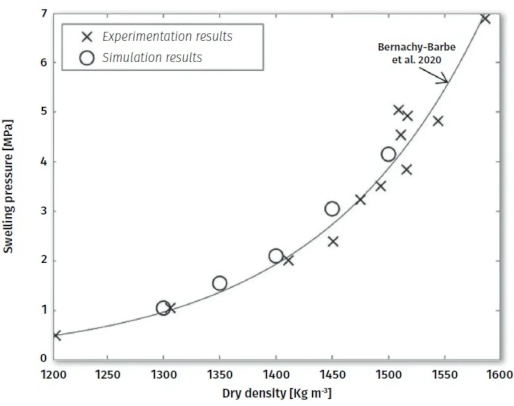
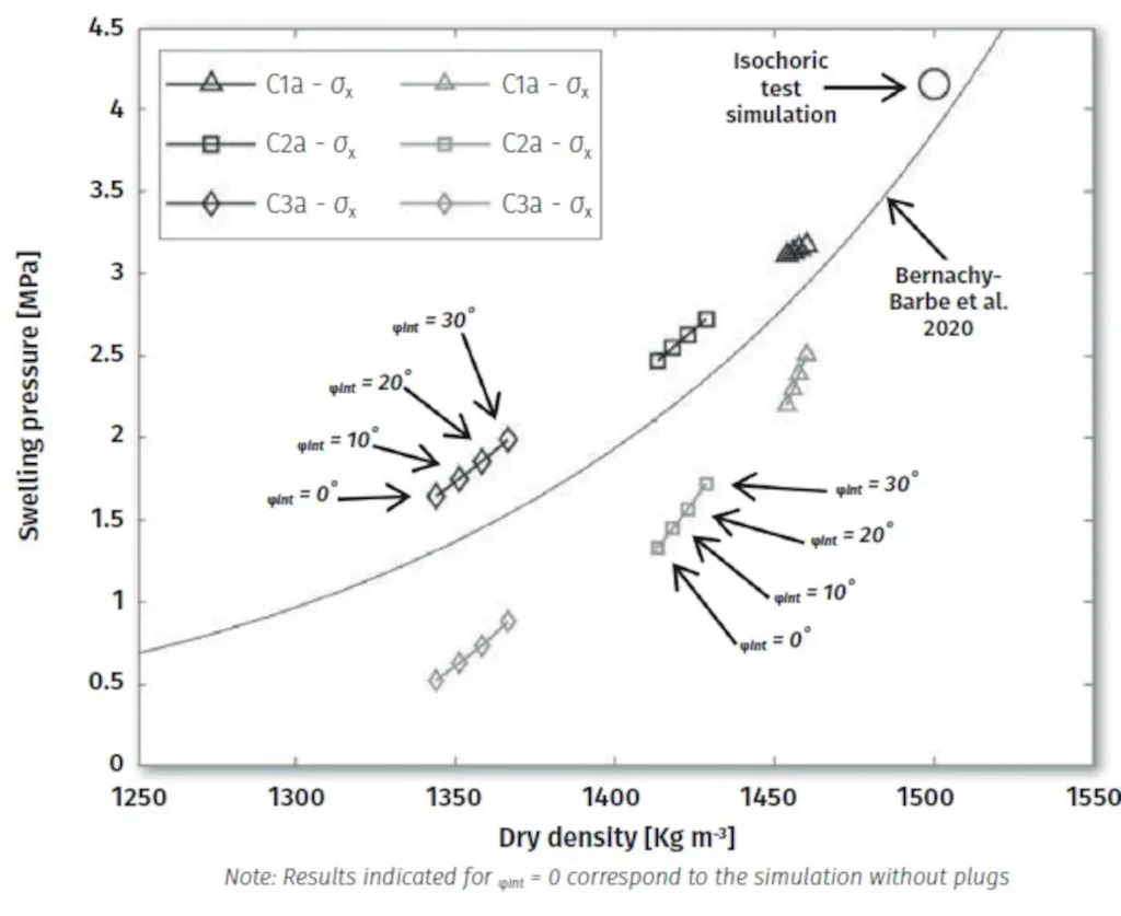
The swelling behaviour of the pellet–powder mixture used in the FSS experiment was studied by Bernachy-Barbe et al. (2020). Figure 7 shows the results reported by these authors corresponding to constant volume swelling pressure tests carried out on samples at various dry densities ranging between 1200 kg.m-3 and 1600 kg.m-3. An exponential fitting curve proposed by these authors is presented. An increase in swelling capacity with increasing dry density was observed, as well as significant loss of swelling potential with a relatively small loss of density. On average, a final swelling pressure of around 4 MPa was obtained for the samples with dry density similar to the FSS experiment, which is assumed as the target value for the case described.
Other experiments carried out with this kind of mixture systematically show that swelling potential of bentonite powder–pellets mixtures strongly depends on material dry density (Imbert and Villar 2006; Hoffmann et al. 2007). The parameters for the BExM were calibrated to reproduce this effect. For this purpose, five different constant volume swelling pressure tests were simulated, considering initial dry densities from 1300 kg.m-3 to 1500 kg.m-3 in 50 kg.m-3 steps. A comparison between model results and experimental data are shown in Figure 7.
Constitutive Model for the Backfill Material
The backfill material consists of disaggregated and recompacted COx claystone. It is to support the compression exerted by the concrete plugs when sliding under the pressure of the swelling core. The reaction of the backfill is governed by its own stiffness and strength, and is an important force component in the final mechanical equilibrium of the concrete plug.
Because the backfill is initially unsaturated, BBM is employed as constitutive law. The BBM is able to represent many of the fundamental features of the behaviour of partially saturated soils under compression, and allows consideration of possible irreversible deformations (collapse) during the hydration of the soil. For the sake of simplicity, since the expansive behaviour of the backfill material is limited, and reversible swelling deformations contemplated in the formulation of the BBM are neglected.
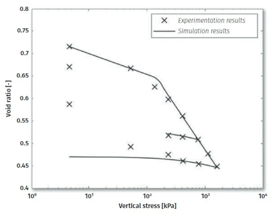
Parameters for the backfill material were calibrated reproducing oedometer tests performed for Andra by LAEGO- ENSG (Laboratoire Environnement, Géomécanique & Ouvrages—Ecole Nationale Supérieure de Géologie). Comparison between experimental results of a reference oedometer test reported by LAEGO-ENSG and the results obtained from the simulation are shown in Figure 8.
Constitutive Model for the Compressible and Concrete Lining
The lining consists of two layers: the internal layer of B60 grade concrete (uniaxial compressive strength of 60 MPa); and, the external layer made from a compressible material formed from crushed COx claystone.
The compressible material, installed between the concrete lining and the host rock, exhibits a high deformability. It is intended to allow for the convergence of the excavation wall due to the time-dependent deformation of the host rock. This is an innovative feature that aims to reduce the transmission of forces to the concrete lining, thus reducing its thickness. Each layer (concrete and compressible material) has been simulated separately considering a specific constitutive model for each.
According to concrete lining specifications, compressive stresses should remain below 50% of the maximum compressive strength (60 MPa). Consequently, it is expected that the concrete lining remains elastic during the full time of simulation. However, the concrete lining around the sealing core could reach the maximum tensile strength of the concrete (5 MPa) under the pressure exerted by the expansive material during swelling. For this reason, an elastoplastic model is employed. When the maximum compressive strength is reached, the response is assumed perfectly elastoplastic, while when the maximum tensile strength is reached, a brittle failure occurs and the tensile strength is assumed to be zero.
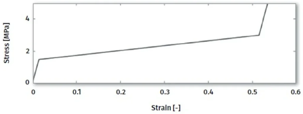
The behaviour of the compressible lining material is characterised by three regimes (Souley et al. 2017; Zghondi et al. 2017): a stiff response for a radial strain up to ~ 1.5%; a high deformability limiting the radial stress within a range of ~ 2 MPa –3 MPa for radial strain up to ~ 50%); and, a stiff response for radial strain higher than 50%. For simplicity, at this stage, this response is simulated through a three-step linear elastic law (see Figure 9). The values of Young’s modulus adopted for the three branches are in accordance with the specifications given by Andra for the material.
RESULTS
The discussion of the simulation results is in four parts: first, the EDZ creation during the excavation procedure; second, natural hydration and performance of the sealing core; third, equilibrium of the whole system; fourth, recompression of the EDZ.
Excavation-Induced Damaged Zone
As part of the Meuse/Haute-Marne Underground Research Laboratory (MHM-URL) programme at Bure, experimental studies were performed to characterise the response of the COx claystone to different drift excavation methods. The experiments showed that the fracture patterns and the extension of the fractured zone around the drifts depend essentially on the drift orientation (Delay et al. 2007; Armand et al. 2013).
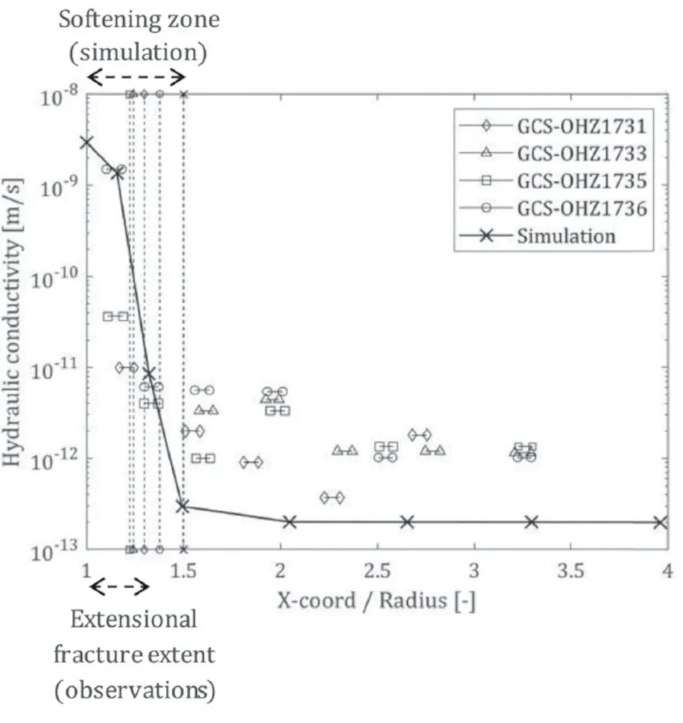
Figure 10 shows the conceptual model proposed by Armand et al. (2014) for the induced fractures network observed around a drift when the excavation is aligned with the major principal horizontal stress. It was observed that despite the nearly isotropic in-situ stress state perpendicular to the axis of the tunnel, the extent of the fractured zone is markedly larger in the horizontal direction compared to the vertical, indicating the important role played by the inherent anisotropy of the rock.
The modelling of the development of localised fractures during excavation would require the use of advanced numerical techniques intended to provide objectivity to the obtained solution. As previously noted, the huge computational resources required for large 3D geometries makes such application currently impracticable. The fractured zone will thus be represented as the zone of development of shear plastic strains predicted by the hardening/softening model.
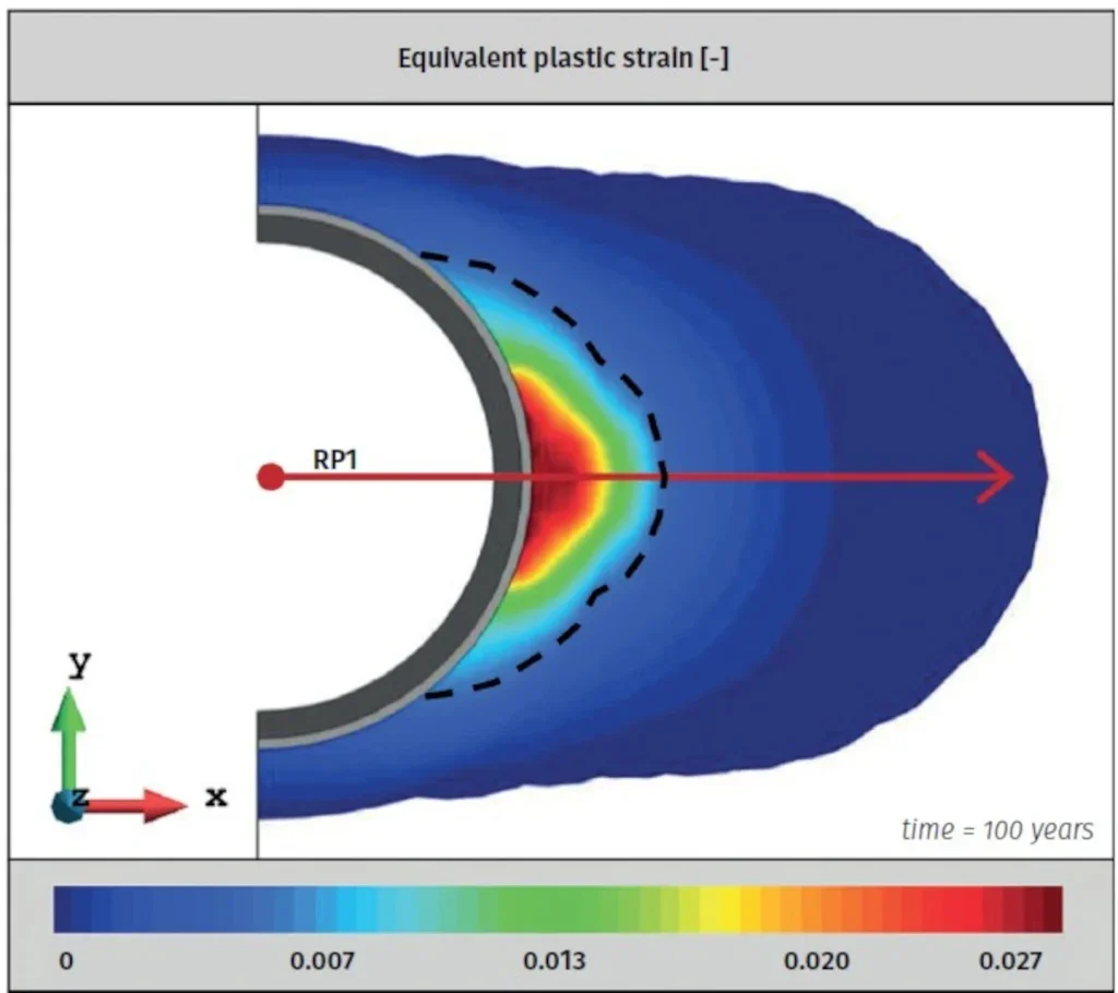
In Figure 11, contour values of the equivalent plastic strain are presented for t = 100 years. The dashed line delimits the plastic zone. The result describes the state at the end of the operational phase.
Although no regularisation technique was considered, the obtained extension and shape of the plastic zone appear to be comparable with the fractured zones observed in the MHM-URL and schematised in the conceptual model proposed by Armand et al. (2014). This plastic zone will serve as the basis for the modelling of the EDZ and the size of the zone of permeability variations around excavations.
In Figure 12, values of water permeability obtained from the simulation along the radial profile indicated in Figure 10 are presented. The in-situ experimental measurements reported by Armand et al. (2014) for CGS drift are shown, indicating also the extent of the area where extensional fractures were observed. Since the diameter of CGS drift is smaller than the one considered in these simulations, distance to excavation wall has been normalised with respect to the radius.
It can be observed that the simulation satisfactorily reproduces the hydraulic conductivity increment within the EDZ. It can be noted that the extent of the area where extensional fractures were observed around the experimental drift is comparable to the extent of the softening zone derived from the simulation. It is in this zone where the most significant variations of permeability are obtained.
These comparisons are not intended to validate the capability of model to represent the processes occurring during the formation of fractures. The purpose is to show that the obtained plastic zone provides an extension, shape and permeability distribution than can be favourably compared with field observations, setting conditions for an acceptable hydro-mechanical state at the beginning of the subsequent natural hydration phase.
Natural Hydration Process and Seal Performance
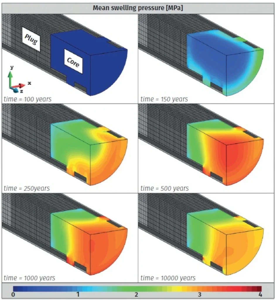
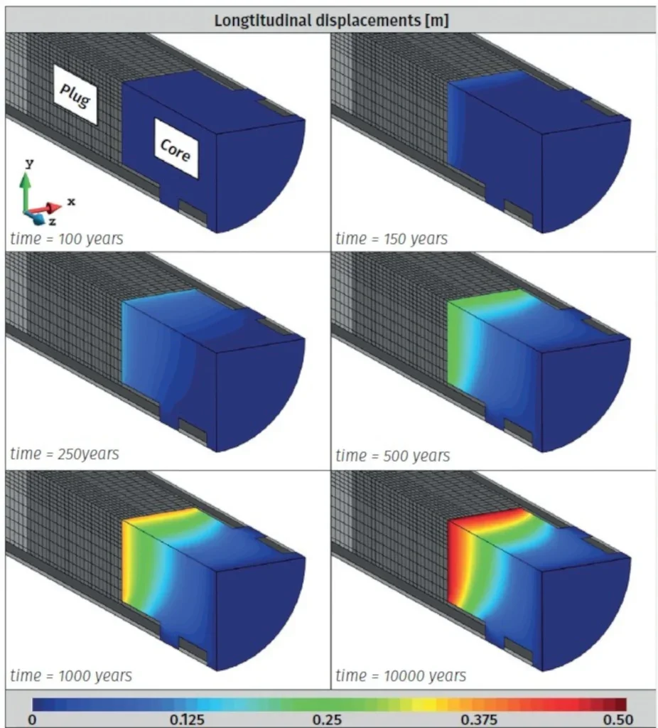
In Figures 13 & 14, the spatial distribution of degree of mean swelling pressure and longitudinal displacements in the core are presented for different times. For ease of viewing, the upper half of the model is hidden. Contours values correspond to time steps from t = 100 years (initial state, after sealing structure construction) to t = 10,000 years.
In Figure 15, time evolution of core degree saturation, dry density, and the radial and longitudinal component of swelling pressure are presented for six points within the core indicated in Figure. 6 – C1a,b; C2a,b; C3a,b – all contained in the plane “x–z” (y = 0 m).
Time evolutions of saturation indicate that the expansive core is progressively hydrated in the radial direction from the perimeter towards the centre, and are of concern to the kinetics of hydration and not total duration. All the points reach full saturation more or less at the same time, around 2000 years after seal construction (dashed line labelled as “Sat. t ~ 2000 y” in Figure 15.
From the observation of dry density time evolution, the central part of the core increases during the initial hydration process, related to the core first hydrating and swelling close to the host rock, which results in a compression at core centre. As time and hydration proceeds, all the core shows a general reduction of dry density due to deconfinement resulting from movement of the concrete plugs (see longitudinal displacements in Figure 14).
On the time evolution of swelling pressure (Figures 13 & 15), it increases towards a maximum value that is less than the target swelling pressure (4 MPa). The final values reached at the different points relate to dry densities obtained at each. Thus, at the core, the result of the final non-uniform distribution of core density is a non-uniform distribution of final swelling pressure.
A second observation relies on the difference between the radial and longitudinal components of swelling pressure, where it is noted that the latter is systematically lower than the former, due to displacement constraints: in the longitudinal direction, the swelling pressure is controlled by plugs sliding; in the radial direction, the displacement is almost totally restricted by the concrete lining, where not removed, and by the host rock in the deposition zone.
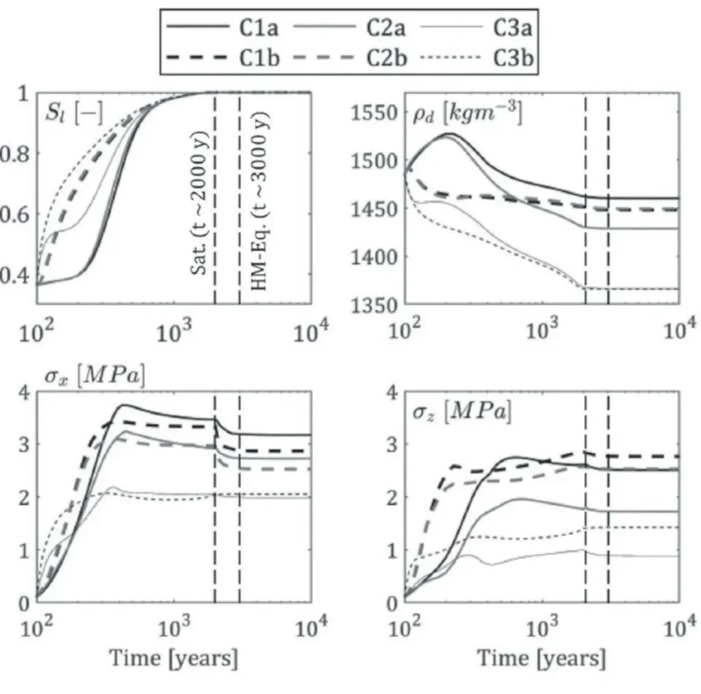
Moreover, it can be noted that final hydro-mechanical equilibrium with hydrostatic conditions and the supporting elements (plugs and backfills) is reached after an additional 1000-years after full saturation (i.e., a total of 3000 years after construction—dashed line labelled as “HM- Eq. ~ 3000 y” in Figure 15. During this period, the total radial stress increases following the rise of the water pressure back to its far-field value, while the effective radial stress slightly decreases to adapt to the small deformations that develop in the host rock and compressible material during the final hydromechanical equilibrium.
Finally, it can be noted that, despite the deconfinement and the general reduction of dry density, the central part of the core maintains a swelling pressure which can be considered within the admissible design range.
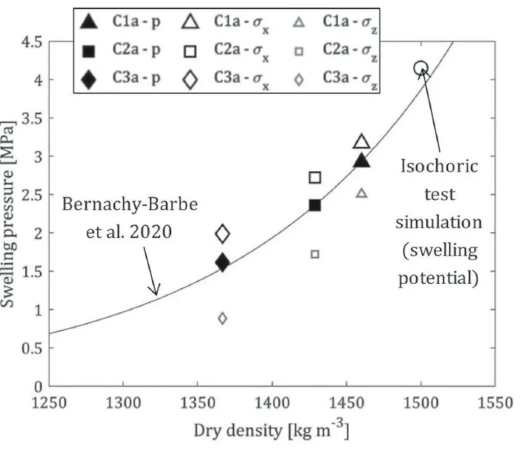
The response and general performance of the expansive core can be summarised in Figure 16 by plotting the final swelling pressure against the final dry density at core points C1a, C2a, and C3a. The reduction of density and swelling capacity clearly affects the whole core and increases progressively from the central part to the end close to the concrete plugs. An interesting aspect is that the relationship between mean swelling pressure and dry density follows the Bernachy-Barbe et al. (2020) fitting curve, as the wetting process is monotonic in both the laboratory tests and the simulation.
From a simplified point of view, stress development within the core can be viewed as controlled by:
- Longitudinal stress dissipation by friction at core perimeter during concrete plug sliding;
- Longitudinal swelling pressure decrease due to progressive loss of constant volume condition, dependant on volumetric deformation imposed by concrete plug displacement and on the material density–swelling pressure relationship; and,
- Radial swelling pressure decrease due to the longitudinal and mean swelling pressure decrease. The radial stress controls, in turn, the friction at core perimeter.
System Equilibrium and Plug-Lining Interface
The longitudinal displacements shown in Figure 14 provide information about the performance of the concrete plugs and backfill material to support the pressure exerted by the sealing core. The maximum longitudinal displacement obtained at the end of the core in contact with the plugs (z=10m) is around 0.5m.
The shear strength of the interfaces between supporting elements and lining (i.e., concrete–concrete interface and backfill–concrete interface) and the reaction of the backfill (governed by the stiffness and strength of the material) are the principal mechanisms contributing to the final equilibrium. Total shear strength of the interfaces is controlled by the friction angle and the normal stress existing at the contact.
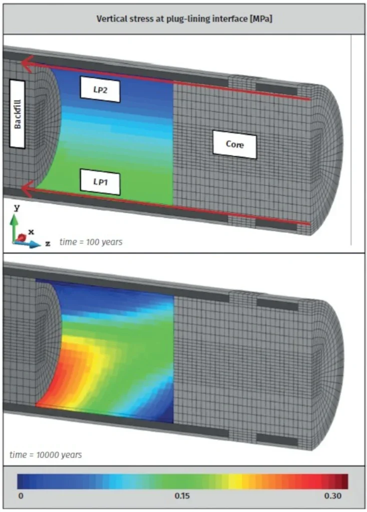
In Figure 17 contour values of vertical contact stress at the interface between the plug and the lining are presented for time steps t = 100 years (after the operational phase and just after sealing structure construction) and t = 10,000 years. For ease of viewing, the concrete plug is not shown in the figure.
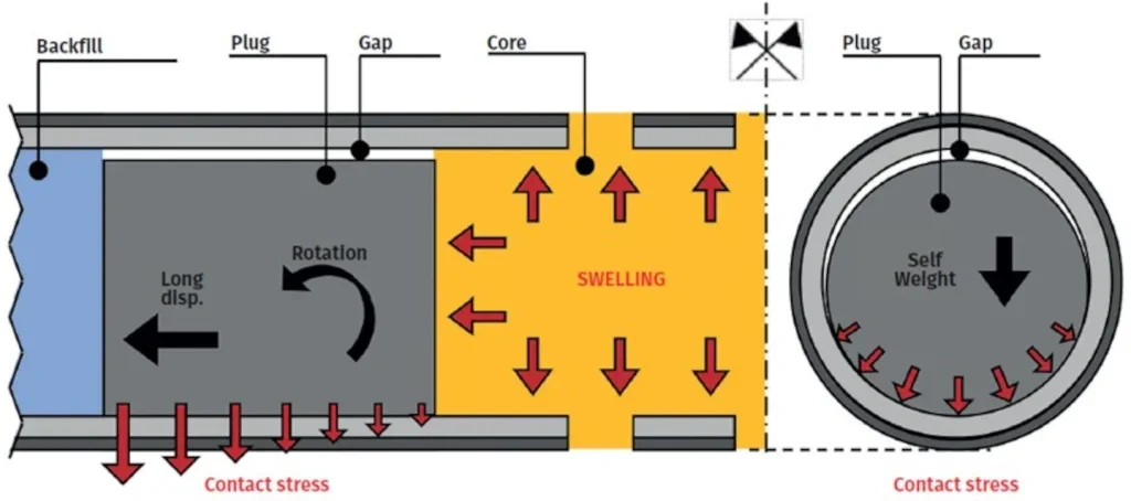
The movements of the plugs are schematically drawn in Figure 18. Before swelling, the contact stress is given only by the self-weight of the materials: it is high at the bottom and low or even null (gap formation) at the top of the gallery. As time proceeds and the core swells, the plugs slide in the longitudinal direction and rotate, as occurs in a gravity wall under earth pressure. The vertical stress at the bottom is therefore higher close to the backfill and lower or even null close to the core.
Despite the self-weight of the plugs and the effect of rotation during core swelling, the contact stress remains below 0.30 MPa. This limits the effectiveness of the concrete plugs as confining elements whatever is the value considered for the interface friction angle.
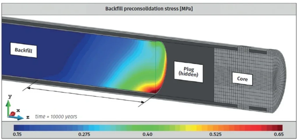
Backfill experiences plastic deformations under the longitudinal compression exerted by the plug. This can be deduced from Figure 19, which shows an increase of the preconsolidation stress. The zone experiencing plastic deformation extends up to a distance of around twice the excavation diameter (~ 20 m).
To study the effect of plug-lining interface strength on performance of the sealing structure, three different simulations were performed, considering different values for the interface friction angle. An additional complementary simulation was performed without the presence of the plugs, corresponding to the scenario in which these elements do not contribute to equilibrium (only backfill material confining the sealing core).
Naturally, longitudinal displacements obtained are higher for lower friction angles. Accordingly, the swelling pressure is reduced due to deconfinement. This effect is more evident at the end of the core where radial and longitudinal component of swelling pressure are reduced by 20% and 40%, respectively, with respect to the reference case.
However, values of the radial and longitudinal stress components in the central part of the core are only 2% and 12% lower, respectively, indicating that the central part of the core maintains the swelling pressure even if the shear strength of the plug-lining interface is reduced or if the plugs are removed.
In Figure 20 the final swelling pressure (radial and longitudinal components) obtained in the different simulations is plotted against final dry density at points C1a, C2a, and C3a. In this figure is also shown the fitting curve already presented in Figures. 7 and 16, derived from the experiments performed by Bernachy-Barbe et al. (2020). It can be observed that, in general, the reduction of the interface strength implies a reduction of the final dry density, and therefore of the final swelling pressure. However, in this case, the effect of decompression on core performance is limited as it is located only close to the ends of the core.
EDZ Recompression
Creep strains lead to a significant increment of radial stress during the operational phase (first 100 years). The radial stress increases by nearly 1 MPa during this period. Afterwards, during the post-closure phase, the increment of stress due to host rock long-term deformation is minor and is limited by the presence of the compressible lining, which allows the rock to deform without increasing the stresses in the lining.
After core saturation, recompression of the EDZ only occurs in the part where the lining was removed allowing a direct contact between the rock and the core. At the sections where the lining is not removed, the presence of the compressible lining does not allow the transmission of the pressure exerted by the core towards the host rock.
CONCLUDING REMARKS
Advanced simulations have been performed to assess the performance of large-diameter sealing structures in the framework of a deep geological radioactive waste disposal in an argillaceous host rock, for the current sealing concept in the Cigéo facility, in France. Large 3D models have been developed including the main components of the sealing structure (expansive core, retaining plugs, and backfills), and key details at smaller scales (such as compressible linings and interfaces).
The presented formulation tackles the strongly hydro- mechanical coupled phenomena related to the excavation, exploitation, and post-closure phases of the disposal. Advanced constitutive models were employed, able to reproduce most of the important aspects of the behaviour of the involved materials.
In particular, the BExM and a non-linear hardening/ softening and time-dependent Mohr–Coulomb based model were considered for the expansive core material and for the Callovo-Oxfordian claystone, respectively. Several complex phenomena underlying the response of the sealing structures were contemplated, such as the EDZ generation during the excavation procedure, the natural hydration of the core, the swelling pressure development, and the achievement of the final equilibrium of the whole system.
These challenging simulations provided qualitative and quantitative results on key aspects about the performance and long-term integrity of the, proving to be a useful tool to support the design and the optimisation of a safe radioactive waste disposal.
Results show that, during the post-closure phase, the EDZ is recompressed by the swelling of the core and part of the initial stresses are recovered. Due to the presence of the compressible lining, the recompression of the EDZ only occurs in the part where the lining was removed and there is direct contact between the rock and the core.
On-going research is aimed at including additional effects, such as concrete degradation, gas flow passing through the sealing system, and self-sealing of induced fractures.
REFERENCES
- Alonso, E.E., Gens, A. & Josa, A. (1990) A constitutive model for partially saturated soils. Géotechnique 40:405–430. https://doi.org/10. 1680/ geot.1990.40.3.405
- Alonso, E.E., Vaunat, J. & Gens, A. (1999) Modelling the mechanical behaviour of expansive clays. Eng Geol 54:173–183. https://doi.org/10.1016/ S0013-7952(99)00079-4
- Armand, G., Noiret, A., Zghondi, J. & Seyedi, DM. (2013) Short- and long-term behaviours of drifts in the Callovo-Oxfordian claystone at the Meuse/ Haute-Marne Underground Research Laboratory. J Rock Mech Geotech Eng 5:221–230. https://doi.org/10.1016/j . jrmge.2013.05.005
- Armand, G., Leveau, F., Nussbaum, C., de La Vaissiere, R., Noiret, A., Jaeggi, D., Landrein P. & Righini, C. (2014) Geometry and properties of the excavation-induced fractures at the Meuse/ Haute-Marne URL drifts. Rock Mech Rock Eng 47:21–41. https://doi.org/10.1007/s00603-012-0339-6
- Bastiaens, W., Bernier, F. & Li, XL. (2007) SELFRAC: experiments and conclusions on fracturing, self-healing and self-sealing processes in clays. Phys Chem Earth 32:600–615. https://doi.org/10.1016/j.pce.2006.04.026
- Bernachy-Barbe, F., Conil, N., Guillot, W. & Talandier, J. (2020) Observed heterogeneities after hydration of MX-80 bentonite under pellet/powder form. Appl Clay Sci 189:105542. https://doi.org/10.1016/j.clay.2020.105542
- Blümling, P., Bernier, F., Lebon, P. & Martin, D.C. (2007) The excavation- damaged zone in clay formations time-dependent behaviour and influence on performance assessment. Phys Chem Earth 32:588–599. https://doi.org/10.1016/j.pce.2006.04.034
- Bosgiraud, J.M., Bourbon, X., Pineau, F. & Foin, R. (2015) The DOPAS full scale seal experiment (FSS): an industrial prototype for Cigeo. Presented at the International Symposium on Cement-based Materials for Nuclear Wastes, Avignon 2014 (NUWCEM 2014)
- De La Vaissière, R., Armand, G. & Talandier, J. (2015) Gas and water flow in an excavation-induced fracture network around an underground drift: a case study for a radioactive waste repository in clay rock. J Hydrol 521:141–156. https://doi.org/10.1016/j.jhydrol.2014.11.067
- Delay, J., Vinsot, A., Krieguer, J.M., Rebours, H. & Armand, G. (2007) Making of the underground scientific experimental programme at the Meuse/ Haute Marne URL, North Eastern France. Phys Chem Earth 32:2–18. https://doi.org/10.1016/j.pce.2006.04.033
- Gens, A. (2004) The role of geotechnical engineering for nuclear energy utilisation. In: Vanicek I et al. (eds) Proceedings of the 13th European conference on soil mechanics and geotechnical engineering, vol 3, Prague, pp 25–67
- Gens, A. & Alonso, E.E. (1992) A framework for the behaviour of unsaturated expansive clays. Can Geotech J 29:1013–1032. https://doi.org/10.1139/ t92-120
- Gens, A., Valleján, B., Sánchez, M., Imbert, C., Villar, M.V. & Van Geet, M. (2011) Hydromechanical behaviour of a heterogeneous compacted soil: experimental observations and modelling. Géotechnique 61:367–386. https://doi.org/10.1680/geot.SIP11.P.015
- Gens, A., Alcoverro, J. & Blaheta, R. et al (2021) HM and THM interactions in bentonite engineered barriers for nuclear waste disposal. Int J Rock Mech Min Sci 137:104572. https://doi.org/10.1016/j.ijrmms.2020.104572
- Hoffmann, C., Alonso, E.E. & Romero, E. (2007) Hydro-mechanical behaviour of bentonite pellet mixtures. Phys Chem Earth 32:832–849. https://doi.org/10.1016/j.pce.2006.04.037
- Imbert, C. & Villar, M.V. (2006) Hydro-mechanical response of a bentonite pellets/powder mixture upon infiltration. Appl Clay Sci 32:197–209. https://doi.org/10.1016/j.clay.2006.01.005
- Manica, M., Gens, A., Vaunat, J. & Ruiz, D.F. (2016) A cross-anisotropic formulation for elasto-plastic models. Geotech Lett 6:156–162. https://doi.org/10.1680/jgele.15.00182
- Manica, M., Gens, A., Vaunat, J. & Ruiz D.F. (2017) A time-dependent anisotropic model for argillaceous rocks. Application to an underground excavation in Callovo-Oxfordian claystone. Comput Geo- tech 85:341–350. https://doi.org/10.1016/j.compgeo.2016.11.004
- Manica, M., Gens, A., Vaunat, J., Armand, G. & Vu, M.N. (2022) Numerical simulation of underground excavations in an indurated clay using non-local regularisation. Part 1: formulation and base case. Geotechnique 72(12):1092–1112. https://doi.org/10.1680/jgeot. 20.P.246
- Noiret, A., Bethmont, S., Bosgiraud, J.M. & Foin, R. (2016) DOPAS work package 4 deliverable 4.8 FSS experiment summary report
- Olivella, S., Carrera, J., Gens, A. & Alonso, E.E. (1994) Non-isothermal multiphase flow of brine and gas through saline media. Transp Porous Media15:271–293. https://doi.org/10.1007/BF00613282
- Ruiz Restrepo, D.F. (2020) Hydro-mechanical analysis of expansive clays: constitutive and numerical modelling, PhD thesis, Universitat Politècnica de Catalunya, Spain
- Seyedi, D.M., Armand, G. & Noiret, A. (2017) ‘Transverse Action’—a model benchmark exercise for numerical analysis of the Callovo-Oxfordian claystone hydromechanical response to excavation operations. Comput Geotech 85:287–305. https://doi.org/10. 1016/j.compgeo.2016.08.008
- Sellin, P. & Leupin, O.X. (2013) The use of clay as an engineered barrier in radioactive-waste management a review. Clays Clay Miner 61:477–498. https://doi.org/10.1346/CCMN.2013.0610601
- Souley, M., Zghondi, J., Vu, M.N. & Armand, G. (2017) A constitutive model for compressible materials: application to the study of interaction between supports and rock mass. Presented at the 7th International Conference on Clays in Natural and Engineered Barriers for Radioactive Waste Confinement, Davos
- Wang, H., De La Vaissière, R., Vu, M.N., La Borderie, C. & Gallipoli, D. (2022a) Numerical modelling and in-situ experiment for self-sealing of the induced fracture network of drift into the Callovo-Oxfordian claystone during a hydration process. Comput Geotech 141:104487. https://doi.org/10.1016/j.compgeo.2021.104487
- Wang, H., Dong, Q., De La Vaissière, R., Vu, M.N., La Borderie, C., Gallipoli, D. & Sun, H. (2022b) Investigation of hydro-mechanical behaviour of excavation induced damage zone of Callovo-Oxfordian claystone: numerical modelling and in-situ experiment. Rock Mech Rock Eng 55:6079–6102. https://doi.org/10.1007/s00603-022-02938-0
- Wileveau, Y., Cornet, F.H., Desroches, J. & Blumling, P. (2007) Complete in-situ stress determination in an argillite sedimentary formation. Phys Chem Earth 32:866–878. https://doi.org/10.1016/j.pce.2006. 03.018
- Zghondi, J., Vu, M.N. & Armand, G. (2017) Mechanical behavior of different concrete lining supports in the Callovo Oxfordian claystone. Presented at the 7th International Conference on Clays in Natural and Engineered Barriers for Radioactive Waste Confinement, Davos


