FIBRE-REINFORCED CONCRETE (FRC) CAN allow the reduction or elimination of traditional reinforcement in precast segment production. Over the past few years, the use of this technology has increased. One aspect boosting the use of FRC in segmental linings was the publication of guidelines for FRC design: in 2013, the International Federation for Structural Concrete (fib) presented Model Code 2010 which included a specific section on FRC. And fib Bulletin 83 provides detailed recommendations for designers, clients and contractors when designing FRC precast segments.
Numerous technical reports have shown the results of one-point load and bending tests carried out on precast FRC segments. The load history, load-displacement diagrams, load-crack opening and the evolution of the crack pattern are highlighted and summarised with pictures relating to each test.
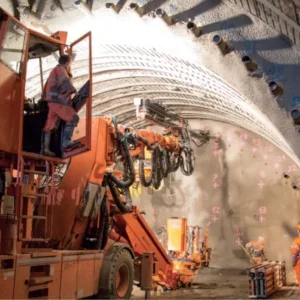
Today, FRC is often used for concrete structures subjected to severe exposure conditions e.g. bored tunnels exposed to saline groundwater containing high levels of sulphates.
The use of SFRC for segmental linings, along with the use of supplementary cementitious materials as partial replacements for ordinary Portland cement (OPC), has significant beneficial effects regarding CO2 emissions. The lessons learned from many projects have confirmed that durability and sustainability go hand in hand.
This paper presents the latest developments in concrete technology achieved from recent tunnel projects using fibre-reinforced precast segments to achieve high performance, a 120-year design life and an ecofriendly product.
INTRODUCTION
Steel fibres have been used to reinforce concrete since the early 1970s. Employed initially for applications such as industrial flooring, it was the 1980s which ushered in the start of underground applications, first for shotcrete, then in both precast tunnel-lining segments and cast-in-place final linings.
However, a lack of regulations and standards hampered the spread of FRC for final tunnel linings. With the publication of international design guideline fib Model Code for Concrete Structures 20101, this obstacle was overcome and designers are gaining confidence in working with fibres. The fib bulletin 83 edited in 2017 aims to support designers, clients and construction companies in using FRC for segmentally-lined tunnels in accordance with Model Code 2010. The use of FRC in precast tunnel segments brings several benefits:
¦ The control of cracking during construction phases
¦ Higher impact resistance
¦ Durability advantages at final stage
¦ Cost reductions
¦ Sustainability advantages
¦ Boosting the production process
PRODUCT EVOLUTION An introduction to the behaviour of FRC
FRC is a composite material characterised by a cement matrix and discontinuous discrete fibres, which can be steel, polymer, carbon, glass or natural materials. The characteristics of the materials used, and their dosage affect the final properties of the FRC.
FRC is also significantly influenced by a range of other factors, such as geometry; volume fraction; mechanical properties of the fibres and the bond between them; the concrete matrix; and the mechanical properties of the matrix.
The behaviour of FRC is more than just a simple cumulative effect of the various characteristics of the concrete matrix and the fibres. As it is a composite material, its behaviour is also impacted by the interaction that occurs between the matrix and the fibres, which means the transfer of load from the concrete matrix to the fibre system.
New generation precast segments
In recent years, the demand has been increasing for higher compressive strength precast segments from C40 to C70. This has been driven by the need for greater structural requirements, to address durability issues, and early-age demolding for increased production capacity. Figure 1 illustrates a typical precast tunnel segment in a ring assembly.
The increase in concrete strength with age and hence better bond with the fibres has led to fibre failure in the cracks rather than bond failure, resulting in a much more brittle behaviour. Fibres provide a more ductile behavior when they are gradually pulled out.
The tensile strength of a steel fibre must increase in parallel with the strength of its anchorage (usual recommended tensile strength is from 1,800MPa minimum to 2,200MPa). Only in this way can the fibre resist the forces acting upon it. Otherwise, it would snap, causing the concrete to become brittle. On the other hand, a stronger wire cannot be fully used with an ordinary anchor design.
One important point to consider is to keep the same network effect. This is essential to ensure consistent behaviour and cracking control.
A fibre with a length/diameter ratio of 80 (60mm length, 0.75mm diameter) offers a network higher than 11km/m3 when the fibre content is 40kg/m3. A minimum network of 10km/m3 is recommended; for this a fibre length/diameter ratio of 65 will need a fibre content of about 55kg/m3
A correct network effect is key to optimise:
¦ Cracking control
¦ Post-crack behavior
¦ Fibre homogeneity and dispersion combined with glued Fibre
¦ Low dispersion in the result.
DESIGN PROCESS
The existing technical guidelines, recommendations and codes (in particular fib bulletin 83 based on Model Code 2010) provide the structural engineer with advice on how to quantify the reinforcing properties of steel fibres based on the measured post-crack tensile strength of SFRC. Figure 2 shows the design process involved, from beam tests, classification, design values, and constitutive laws.
In accordance with fib bulletin 83, Model Code 2010, the structural design of SFRC elements is based on the post-crack residual tensile strength provided by the steel fibres. Nominal values of the material properties can be determined by performing a flexural bending test. One of the most common refers to EN 14651, which is based on a three-point bending test on a notched beam (Figure 3). In order to obtain statistically reliable results, a minimum of 12 beam tests are recommended.
This result shows how a low variation provides a performance class type 5e according to MC2010. The results of such a bending test are expressed in terms of force (F) vs crack mouth opening displacement (CMOD).
Parameters fR,j representing the residual flexural tensile strengths are evaluated from the F-CMOD relationship according to the equation below (simplified linear elastic behaviour is assumed):

Where: fR,j is the residual flexural tensile strength corresponding to CMOD = CMODj
fR,j is load measured during the test (kN)
l is the span length (distance between support) = 500mm
b is the width of the beam = 150mm
hsp is the distance between the tip of the notch and the top of the beam = 125mm.
From the above residual flexural tensile strengths, the characteristic values can be evaluated as follows:
fR,jk = fR,jm – k .Vx
where:
k is the student’s factor dependent on the number of the specimens (12 beams is recommended)
Vx is the standard deviation of the test results.
The standard deviation could be influenced by many parameters, such as mix design, casting, and testing, and is also strongly influenced by the fibre number and network effect. A higher fibre network leads to a lower standard deviation, which is key to achieve the required value for design.
For the classification of the post-crack strength of FRC, a linear elastic behaviour can be assumed by considering the characteristic residual flexural strength values that are significant for serviceability (fR,1k) and ultimate (fR,3k) conditions. Two parameters are especially important, and need to be specified by the designer, namely:
fR,1k: the minimum value for SLS
fR,3k: the minimum value for ULS.
Materials with fR1k ranging from 4MPa to 5MPa are commonly used for precast tunnel segments without any bar reinforcement, combined with a fR3k/ fR1k ratio in the ranges 0.9< fR3k/ fR1k <1.1 or 1.1< fR3k/ fR1k <1.3 (Class C or Class D respectively, according to the Model Code 2010 definition).
Hardening post-crack behaviour at section level (through a beam test) immediately allows for crack control and for SLS design and structural ductility for ULS design.
SUSTAINABILITY Sustainability assessment
The designer of a reinforced concrete, precast tunnel segment tasked with providing a sustainable, TBM-bored tunnel lining must consider not only environmental impacts of the design, but also meet structural requirements because meeting minimum service-life requirements can provide increased durability. When the geology requires the tunnel to be lined, the use of SFRC in a precast tunnel segment, either combined with bar reinforcement or alone, has been found to provide a more sustainable solution over other options.
Determining the environmental impacts of one construction process or another needs to be objectively assessed. The engineer must also consider that reducing the environmental impact of a structure is only one consideration. The structural engineering design of a tunnel-lining segment is primarily dependent upon the load conditions applied to it (ground loads, handling, transportation and erection, as well as live loads). The benefits of reduced embodied CO2 can only be realised when the selected reinforcement specified also meets all the design requirements (structural, safety and durability).
fib Bulletin 83 – Precast Tunnel Segments in Fibre- Reinforced Concrete, contains a chapter entitled 10.1 Sustainability Index. The chapter proposes a method of comparing precast concrete-segment alternatives taking into account the economic, environmental and social requirements involved in the production of the precast segments. The comparison is carried out on three different precast segment alternatives by means of the sustainability and mechanical indexes assessed for each one. The chapter provides a detailed assessment of an example precast concrete tunnel segment using three different alternative reinforcing solutions. It also provides a good reference for engineers who need to perform a sustainability assessment on precast concrete segment alternatives.
Reduced Carbon Footprint
The use of steel and synthetic fibres to replace all or part of conventional reinforcement has been demonstrated to lower the embodied CO2 of the segmental lining. Macro-synthetic fibres are shown to provide a lower embodied CO2 content than steel, however as addressed in section 5.1.1.2 Steel vs Macro-synthetic Fibres, they are unable to meet all the structural/mechanical performance requirements of a precast concrete segment, with limited exceptions.
Therefore, this section will focus on precast segment linings using SFRC to replace rebar/mesh. While it is possible to significantly reduce the embodied CO2 of a concrete mix for segment production by replacing a portion of its cement content with alternative cementitious materials, there is little or no difference between the cementitious blends and contents required for the production of fibre-reinforced or conventionally-reinforced concrete segments for tunnel linings.
A paper by Carola Edvardsen of COWI Denmark entitled ‘The consultant’s view on service life design’ (in CO2 emissions on a project made possible by modification of the life) provides an example reduction of concrete and further reduction by being able to replace the rebar with steel fibres in a dosage that satisfied all of the design requirements.
On a per pound (weight) basis, the embodied CO2 of conventional rebar and steel fibres is assumed the same. This is a generalisation assuming the wire rod that the fibre is produced from and the rebar have similar percentage recycled material content and similar steel production methods. In a precast segment, the reduction in carbon footprint is due to the steel fibres being more efficient in reinforcing the element. In this example, the elimination of 72% of steel by replacing rebar with steel fibres provided a 72% reduction in the embodied CO2 contributed by the reinforcement.
In a precast concrete segment design, the percentage of steel reduction is dependent on the structural and serviceability requirements of the segment, and the fibre’s attributes and performance in the specific concrete mix. Based on information from a leading steel fibre producer, a typical percentage reduction of the steel in a precast concrete segment when using only steel fibres is typically 60-65%. The actual reduction in embodied CO2 of the lining will depend on the contribution from the reinforcement plus the concrete. Table 2 shows that steel fibres used to reinforce concrete segments allow for a reduction in the energy consumed per cubic metre of concrete by 26%, when compared to the classical steel rebar solution.
CONCLUSION
The environmental, economic and increased durability benefits provided using high-performance steel fibres when they replace some or all of the conventional reinforcement in a precast segment is substantial. A durable tunnel that has a long life provides an extended period to amortise the environmental and economic costs that were incurred in building it.
Hypothetically, if the life of a tunnel is doubled, the environmental impacts of its construction are halved. A tunnel designed and built to last 100 years offers significant resource advantages over a comparable tunnel that will last only 50 years. The improved durability of SFRC segments coupled with the fact that their use provides substantial first-cost savings over conventionally-reinforced segments magnify the economic benefits and sustainability of the tunnel.