PROJECT BACKGROUND
Currently, water demand in the western region of Bangkok exceeds the production capacity of the Mahasawat and Thonburi water treatment plants. Additionally, the Metropolitan Waterworks Authority (MWA) has implemented a policy to manage water from the western side of the city to supplement the water supply in the eastern side, where it needs to address challenges posed by saltwater intrusion into the Chao Phraya River.
To overcome this issue, MWA plans to enhance the water production capacity in the western area by expanding the Mahasawat water treatment plant’s capacity by an additional 800,000 m3/day, along with the establishment of a water transmission system, including a tunnel, and valve chambers. Once this tunnel and system are completed, they will enable the water supply from the western side of the city (using raw water from the Mae Klong River) to supplement the eastern side (using raw water from the Chao Phraya River) through the construction of four additional water transmission tunnels.
WATER TRANSMISSION TUNNEL
The total length of the tunnel for the project’s contract GTN9B is approximately 9.1km, and this is divided into three drives with two different diameters. The difference in tunnel diameter is based on the distance from the water treatment plant.
Construction is being executed by a joint venture between ItalianThai Development (ITD) and Nawarat (NWR), under the name ItalianthaiNawarat JV.
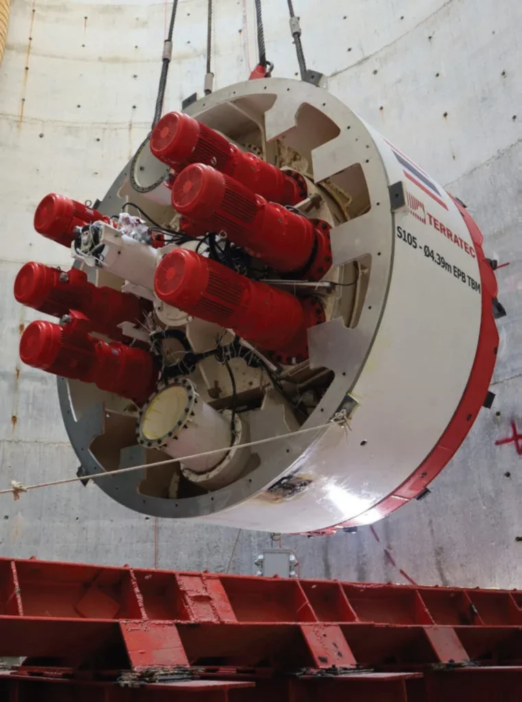
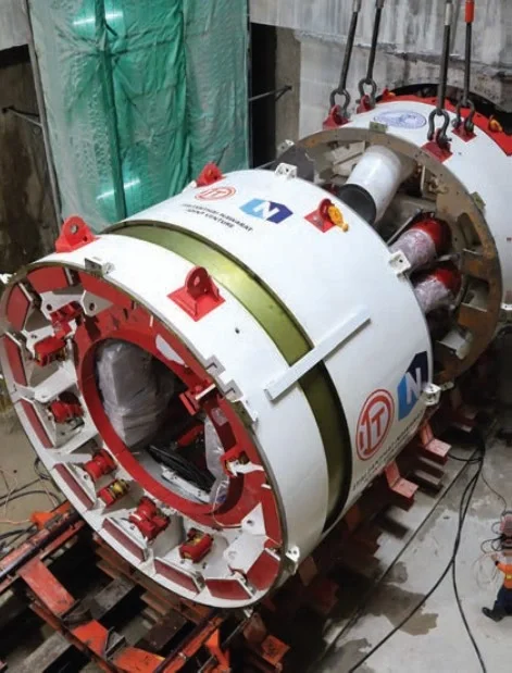
For the three drives, the JV has selected three earth pressure balance (EPB) tunnel boring machines (TBMs) from Terratec to undertake the tunnelling work: one TBM with a diameter of 4.80m (S107 machine); and, two TBMs of 4.39m diameter (S105 & S106).
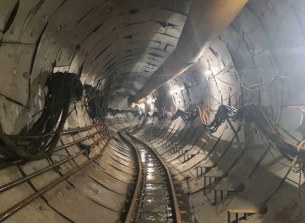
The three drives are segmentally lined, and upon completing the tunnel excavation, steel tubes will be installed as the secondary lining. Infill mortar will be applied in the space between the concrete segments and steel tubes. The space is approximately 200mm wide. The lining system will support internal water pressure within the tunnel, which will range from 5 bar to 8 bar during operation, and to enhance waterflow efficiency.
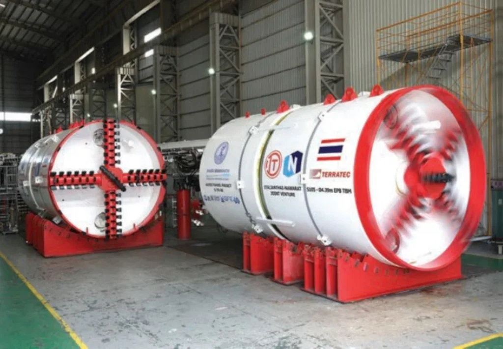
For project section GTN9B, the inside diameter of the steel tubes is specified in two sizes: 3800mm and 3400mm. There is 2,233m of tunnel with the final diameter of 3800mm, and 6,840m of tunnel at the smaller final diameter of 3400mm.
The tunnel alignment is situated in an area of the city managed by the Department of Rural Highway (DORH), which experiences heavy traffic during rush hour. Consequently, the launch and receiving shafts for the TBMs are positioned to avoid creating traffic obstructions, including within roadway medians and beneath flyover bridges.
The alignment creates multiple curves to avoid flyover bridge foundations, with a minimum radius of approximately 80m90m. All TBMs have been designed with activetype articulation to accommodate the specified minimum curve radius.
GROUND CONDITIONS
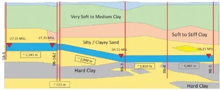
The geological conditions along the tunnel alignment are typical for the Bangkok region, comprising soft clay, stiff clay, silty/clayey sand, and hard clay at varying depths.
For this project, the tunnel is designed to be located at a depth of approximately 27m to 34m from the ground surface, passing through silty/clayey sand throughout the excavation.
While tunnelling through sand can be relatively fast, there is a risk of water and sand ingress into the tunnel, which, in severe cases, could lead to tunnel collapse. Such incidents have occurred in Bangkok in past projects. Therefore, the TBM design and tunnelling team must exercise particular caution and implement necessary precautions.
SHAFT CONSTRUCTION
Five shafts are being constructed, each approximately 40m deep, functioning as launch, receiving, or intermediate shafts.
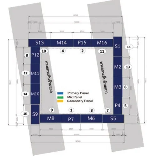
These shafts are constructed using two methods: D-Wall and Caisson Sinking, respectively, depending on site conditions and construction constraints. For example, shafts built beneath flyovers, where low headroom is a concern, have been constructed using the D-wall method which requires specialised machinery such as baby grabs.
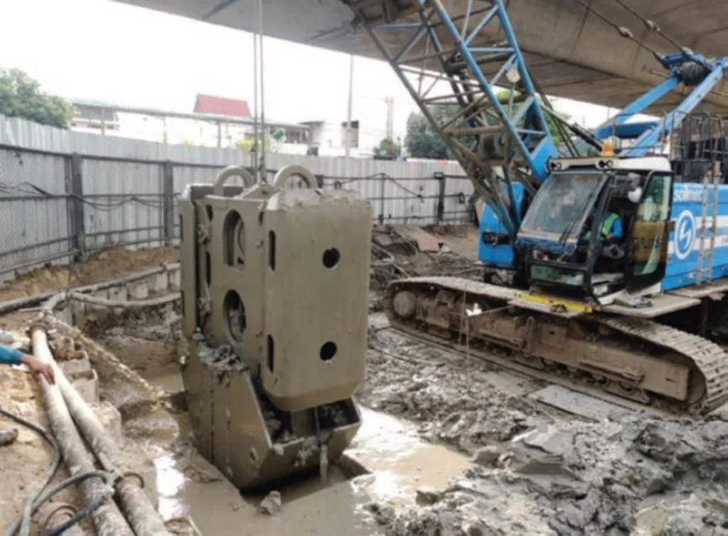
Below are the details of various shafts, their dimensions, construction methods, and uses:
- Shaft 9B-1: Rectangular 16m x 13m, D-Wall, Launch Shaft
- Shaft 9B-2: Rectangular 10m x 10m, D-Wall, Intermediate Shaft
- Shaft 9B-3: Circular ID 8m, Caisson Sinking, Receiving Shaft
- Shaft 9B-4: Rectangular 9m x 6m, D-Wall, Intermediate Shaft
- Shaft 9B-5: Circular ID 13m, Caisson Sinking, Launch Shaft
TUNNELLING
The tunnelling process is divided based on the size and distance of the tunnels.
TBM 2
Work commenced with TBM 2 (Terratec’s S105 machine, 4.39m-diameter), at Shaft 9B-5. Driving from this launch shaft, the TBM will excavate through the intermediate Shaft 9B-4 and continue on to Shaft 9B-3, the receiving shaft.
TBM 1
TBM 1 (S106 machine, 4.39m-diameter) started its tunnelling operations at Shaft 9B-1, to tunnel through 111m to Shaft 9B-2, and the contractor will then relocate facilities to Shaft 9B-2 to continue boring toward Shaft 9B-3.
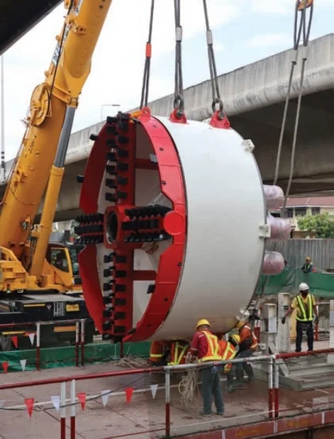
For the deployment of TBM 1 at its launch shaft, located between sections of a motorway flyover, the contractor utilised a 500-tonne mobile crane and a 220-tonne crane. Due to limited space for crane manoeuvrability, a special technique was employed by constructing a temporary platform over the shaft, which allowed the TBM to be positioned between the two cranes and lowered into the shaft.
The tunnelling operation from Shaft 9B-1 to Shaft 9B-2 also presented challenges for the surveying and navigation system, as the tunnel passes in close proximity to the bridge foundation, only some 0.90m away. The short section of tunnel had to be designed with curves, resembling an S-curve, requiring an experienced operator and a TBM with an effective copy cutter system.
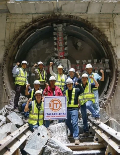
The tunnel has successfully passed this critical section, alleviating concerns for the project team.
Additionally, work conducted under the flyover presented further challenges due to space constraints, requiring a gantry crane for lifting segments and muck cars to be specially designed for optimal functionality in the limited area.
TBM 3
TBM3 (S102 machine, 4.80m-diameter) will begin at Shaft 9B-1 to bore approximately 2.2km.
CURRENT PROGRESS
As of now, TBM2 (S105) has excavated approximately 200m through Shaft 9B-4.
TBM1 (S106) was launched from Shaft 9B-1 and, as noted above has passed the critical section of the S-curve tunnelling at the bridge foundations to reach (Shaft 9B-2). The contractor will relocate facilities to Shaft 9B-2 to continue boring toward Shaft 9B-3.
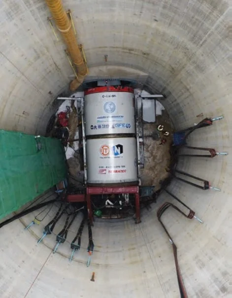
TBM3 (S102) is currently in the process of being lowered into vacated Shaft 9B-1 to commence boring approximately 2.2km in the opposite direction, to connect with Shaft 9A-5 of another contract.
CONCLUSION
The G-TN-9B tunnelling project presents significant challenges in both management and engineering, particularly with its proximity to the flyover’s foundation and the need to operate in constrained areas, such as low headroom zones. Additionally, the geological conditions along the alignment, which consist of highpressure sandy layers, require careful planning and execution.
Effective collaboration among all parties involved in the project – including the project owner (MWA), consultants, contractors (Italianthai-Nawarat JV), and the TBM manufacturer (Terratec) – is essential for successfully achieving the project’s challenging goals.


