As Ahmed Al-Samarray, geologist with Norwegian roads authority Statens Vegvesen (NPRA), tells T&T: “There is a general misconception” about waterproofing measures employed on tunnel projects, such as on the world-beating subsea crossings around Stavanger.
Much of the engineering efforts to establish effective waterproofing solutions is often unseen, and often comprise either plastic sheets or chemical sprays plus solid foam packing, all sandwiched behind the visible linings of precast concrete or shotcrete that drivers easily see passing through tunnels.
In some Scandinavian projects, however, much of the leakage reduction design is located even farther behind the obvious concrete/shotcrete linings, and also beyond the sight of tunnellers – such as when high volumes of high-pressure grout are injected deep and extensively into wet rock to solidify and seal the mass, or at least enough to keep inflows within permitted operational limits for a tunnel. The method is pre-excavation grouting (PEG) and significant use is anticipated in Stavanger’s Rogfast project.
Frost insulation is also important in some parts of portal zones of tunnels in cold regions, and often, foam packing is placed behind the concrete lining. Lengths vary for stretches to receive frost protection, dependent on regional as well as local micro-climate differences, plus also the tunnel size, and the direction and frequency of traffic flow.
While waterproofing solutions vary with the many different aspects of projects, and can have different applications along the length of a single tunnel, Al-Samarray says the designs are broadly divided into classes to achieve desired leakage and thermal performance. The two key factors which can help designers achieve the long-term performance, he adds, are the annual average daily traffic (traffic load) and tunnel length, respectively.
Beyond the construction stage, waterproofing systems must be checked to ensure their integrity and ongoing performance, or be improved if needed – such as during rail tunnel refurbishment in Bergen, Norway – or have remedial repairs – such as fixing the sudden, unexpected inflow of sediment and water into the live Lotschberg Base Tunnel, Switzerland.
SOLUTIONS FOR STAVANGER
With two of the world’s longest subsea road tunnels in its neighbourhood, the coastal city of Stavanger has become a hotspot of tunnelling after decades of servicing much of Norway’s offshore oil and gas industry. Local mega tunnelling experience has included construction of the Ryfast subsea tunnel within the last decade, and opened in early 2020; this decade will see the focus on the much larger Rogfast project which will become the world’s longest subsea road tunnel. Both Ryfast and Rogfast are twin-tube fixed crossings, featuring regular cross passages.
When preparing for such large projects to run through the rock deep below fjords, and including for the design of waterproofing and frost protection, Al-Samarray says the first step starts “early in the planning stage” with a ship-based seismic survey to map geological conditions. The investigations provide data to help establish the thickness of seabed sediments which can work as a protective layer, he says.
Once tunnelling is eventually underway, further data comes from systematic probing ahead of the face, along the full length of each tunnel, allowing samples and inflow rates to be checked against expectations for the local rock mass and groundwater regime. Al-Samarray explains that typically, four holes, each up to 21m long, can be bored; the inflows are subsequently measured against the allowable leakage limits for the locality. Then, if needed, PEG may be undertaken to reduce, or eliminate, the inflows.
The third main step in preparing the water protection measures (and frost protection, too, if needed), is then undertaken: the design and placement of layered systems, which are the visible element of the protection. The measures can include placing foam, membrane/ spray, concrete panels or shotcrete. Again, the length of tunnel involved – and also the anticipated traffic volumes – will affect the degree and type of protection solutions adopted.
Choices for particular water and frost protection, therefore, vary between Ryfast and Rogfast subsea tunnels, even though they are relatively close. But Statens Vegvesen has some baseline standards for types of linings – also dependent on sizes of the tunnel cross-section – which progressively move from shotcrete to using more precast concrete elements.
While more expensive to install, precast panels provide combinations of better traffic safety, fire protection, life span and are easier to maintain and replace during the long operational life of a tunnel project, says Al-Samarray.
RYFAST
The Ryfast road system has three main tunnels – the 14.4km-long Ryfylke Tunnel that dives under the fjord; the Hundvag Tunnel that slips at shallower depths below small islands toward the city; and the Eiganes urban tunnel below Stavanger itself.
The tunnels vary in terms of length, size and volume of traffic carried:
? On the shorter Eiganes (3.7km) and Hundvag (5.5km), the visible waterproofing runs for the total tunnel lengths, comprising PE foam in an arch over the entire cross-section profile, behind precast concrete panels at the side walls and shotcrete overhead.
? As for Ryfylke, says Al-Samarray, water protection involves PE foam and shotcrete but used only where needed, in sections of tunnels with droplets or moisture. Ryfylke has a T8.5 profile (8.5m wide at road level, and 4.6m-high designed vehicle clearance), and descends to 290m below sea level.
Al-Samarray says the design choices arose from a combination of reasons with Eiganes (T9.5 profile) and Hundvag (T8.5) being more heavily trafficked and running below urban areas. In terms of grouting, the PEG on them had to achieve stricter leakage limits (1.5 – 2.5 lit/min) compared to Ryfylke (up to 5 lit/min tolerated), even though the latter runs below the fjord. And, being in the west of the country, which is less cold, only limited frost protection is placed, not around the entire profiles but near portals only.
In terms of performance, the waterproofing on all these tunnels has worked well, explains Al-Samarray, with only a “few spots showing water drops” requiring a degree of improvement in Ryfylke. Excavated over 2013- 17, Ryfylke was fitted out and opened to traffic almost two years ago.
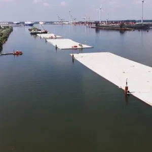
ROGFAST
To be the world’s longest road tunnel of its type, and for reasons of ‘best water protection and traffic safety,’ the entire length of the 26.7km long Rogfast Tunnel is to have waterproofing membranes and precast concrete panels forming the entire profile, says Al-Samarray. In terms of frost protection, the provisions will be as with the Ryfast road tunnels, extending up to 200m from the portals for the same local climate reasons.
Main excavation on the first of Rogfast’s three tunnelling lots recently began and will be undertaken by drill and blast, as used for Ryfast. The twin main tunnels will have T10.5 (10.5m wide at road level) profiles.
NEW AND OLD FOR BERGEN
The design approach for waterproofing on the existing and parallel new rail tunnel into the port city of Bergen, farther up the Norwegian coast, also employs plastic (PE) membrane and shotcrete. Some rock grouting, too, has its place in the measures.
Rail authority Bane NOR is investing in the project to overcome a severe bottleneck in its network which, for decades, only had a narrow single tunnel running through mountains to serve Bergen. The project has involved driving a new, generally parallel, 7.7kmlong tunnel (called New Ulriken) and, with that now operational, efforts have switched over to refurbishment of the old tunnel.
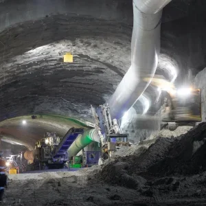
For the new tunnel, only limited drill and blast excavations were performed. Contractor Skanska- Strabag JV used a Herrenknecht TBM to bore most (6.9km) of the new tunnel from the east side (near Arna station) toward Bergen, stopping short at the west portal, at Floen. The shield drive through mostly banded gneiss was performed over 2016-17.
Bane NOR’s tunnel project manager, Torstein Standal, tells T&T that the rail authority’s technical requirements for new tunnels allow for three types of general waterproofing arrangements in new tunnels: full cast-concrete ring with membrane; shotcrete with spray membrane; and segmental lining if placed in TBM drives. He adds that the requirements “are not so specific” for refurbishing existing rail tunnels, although some requirements by necessity must be fulfilled, such as having products with sufficient fire retarding and tensile strength qualities.
For New Ulriken tunnel, excavations left much of the rock visible. The JV’s work also included waterproofing and frost protection measures. Waterproofing in the new tunnel comprises PE membrane (Oldroyd Multisafe 1200 R) with rebar and 80mm thickness of shotcrete cover, says Standal. The tunnel was opened to traffic a year ago and refurbishment of the old tunnel then began.
The original tunnel is ‘relatively dry,’ he says, and only a little over a fifth – over about 1,500m in total – needs water protection. To reduce the cost, water protection is to be added where leakage droplets fall in the rail area and risk degradation of the infrastructure over the long-term, Standal adds. Droplets outside the rail area will not be handled.
“Since our main concern is droplets at the rail, over winter months to February 2021 ,the project performed localised spot grouting with PU and colloidal silica in the old tunnel’s roof arch rock, plus a thin layer of shotcrete, to see if we could move the water away from the rail area.”
Standal estimates the success rate to have been limited, at about 16%, he tells T&T, for a few reasons:
? Not the ideal equipment for depth of drilling (only 3m maximum).
? Due to the thin layer of shotcrete for rock support it was difficult to follow the cracks and see where the water moved.
? Trouble with packers.
? Persisted too long in the spot grouting effort in the most difficult areas.
? Logistical limitations due to single-line working on the track over a 5km stretch while other activities were also being undertaken, which lead to insufficient time for the task.
While the shotcrete is in some areas for rock support, Standal says that it was not part of the previous waterproofing system which relied on PE foam, and also as such did not comply with fire retardation regulations. But although the easiest construction solution would be to spray shotcrete on competent PE foam, “the profile is too narrow for this, and therefore we have to drill and blast to make room,” he adds.
He says enlarging the old tunnel profile will provide space for the waterproofing layers and sufficient fire retardation, and also to house new ventilation and catenary power systems in certain locations. The expansions have called for about 200mm extra depth of rock taken out, all round the profile, to hold either PE membrane or PE foam, steel rebar mesh, and a final 85mm-thick layer of shotcrete. To house M&E equipment, the additional excavations are even larger, locally – creating up to about 2m of extra space.
“Due to the quite small profile,” he adds, “we have high loads from the pressure wave caused by the traffic.” The design has the waterproofing system to be fixed on a grid of M24 bolts, set in a 1.2m-square spacing, over the entire profile.
With the excavations almost complete, installation of the waterproofing and frost protection layers is due to begin in November 2021. The first part of the old tunnel (1,200m at the east end, closest to Arna) is due to go into service again at the end of 2022, and the remainder of the tunnel shortly after, just over a year from now, he tells T&T. The contractor on the old tunnel is Azvi Norge, the subcontractor for excavations is Flage Maskin, and waterproofing and frost protection is undertaken by W Giertsen Tunnel.
LEAK IN LOTSCHBERG
Excavating to create more space as part of a water ingress solution has also featured in the operational Lotschberg Base Tunnel, but in a far bigger, albeit localised way. The owner-operator, Swiss rail company BLS, opted to carve out a cavern as a key part of the major drainage solution, effectively creating a sand trap for sediment carried in groundwater inflows.
The problem for BLS appeared in early 2020 when trains were unexpectedly splattered a few times by sand slurry, on separate occasions, as they passed through the live east tunnel. No accidents resulted.
Investigations followed and developed a theory that a drainage pipe, placed as part of the original construction of the project, had been blocked. The pipe drained a karstic zone and it was suspected that conditions had changed, leading to more sediment load than the pipe could convey safely. Pressure build-up followed, the pipe was damaged and the slurry then suddenly entered the live rail tunnel bore. The installation of temporary steel sedimentation tanks accommodated the ongoing flow and had to be emptied of sand weekly.
Lotschberg is one of the major Alpine projects designed with twin-bore running tunnels – except it does not have them operationally, at least not yet. It almost did, until budget constraints left the project mostly excavated but only partly fitted out with rail track and signalling, creating bottleneck operating conditions for rail traffic until funding would later be found to complete the project. Presently, the east tunnel is complete and operational but only part of the west tunnel is fitted-out, although much has been excavated.
A plan for major works to fully complete the twin tunnels, and involving extra excavation for the last sections plus fit-out of dormant tunnels, was being developed when the slurry drainage problem hit near one end of the completed and operational east tunnel.
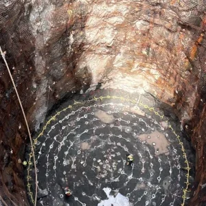
Using diversions through the west tunnel, to isolate the problem zone in the east tunnel, BLS pushed ahead with the remedial works from August 2020 to February 2021. The tunnelling and construction works broke out of the tunnel lining, confirmed the suspected pipe blockage, and the side cavern was excavated. About 10,000m3 of excavation was performed in total for all tunnelling works required to carve out the large chamber, which is positioned parallel, and offline, from the east tunnel, and is accessed by new cross passages.
The inflow is tapped and conveyed to the large cavern, which houses concrete settling tanks to receive the flow. Slowed down, the sand settles while the groundwater flows out and into the Lotschberg drainage system. The sedimentation tank has a more than 2,000m3 capacity and will be regularly emptied into rail wagons as a new task in the base tunnel’s maintenance regime. Ongoing monitoring of groundwater, sediment load and karstic conditions is a further task.