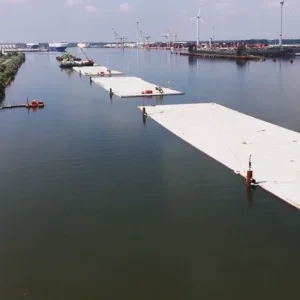
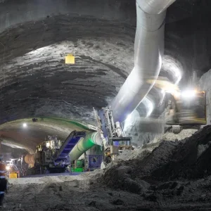
Over the past few decades, pipejacking has proven its worth as an economic and environmentally sound alternative to open cut installation of new pipelines. However, during the installation procedure, the jacked pipes are subjected to exceptional loads, particularly where the pipe route design is not ‘straight’ and/or soil conditions are difficult. Test and inspection concepts used for pipejacking situations have, until recently, been restricted to individual pipes and joints only, ignoring the pipe string bed and curvature.
It was this background that led to a research project being conducted by IKT – Institut für Unterirdische Infrastruktur (Institute for Underground Infrastructure) in Germany. With financial support from the Ministry of the Environment of the German state of North Rhine Westphalia and the Emschergenossenschaft, a testing system was developed which simulated the jacking loads exerted on pipes and pipe joints and showed the resultant bed stresses, on a simulated 1:1 scale.
The results that can be obtained from the simulator can be used to develop recommendations for optimising pipe joints, for planning and control of pipejacking operations, and for on site instrumentation support. The testing system also enables modelling of various pipe loading scenarios during jacking.
Background
In the North Rhine-Westphalia region of Germany alone, annual investments of around US$675M are planned for the construction of new drain and sewer systems. Some US$203M/annum will be used for the reconstruction of the Emscher system. Large sections of this work will involve pipejacking of large diameter pipes of up to ND 2800. Therefore the quality of the jacking pipes and jointing methods will be very important. The risk potential for damage, such as cracking and spalling, must be minimised using appropriate Quality Assurance provisions. It was these demands on engineers that prompted the financial support organisations of the IKT research project to fund the work.
The basic test procedure, process control system and monitoring equipment were first validated using model tests on a ND 400 pipe string, comprising five concrete test pipes. This was then scaled up for test pipes with a nominal diameter of ND 1600 (or 2100mm external diameter).
Concept
Development of the IKT pipejacking simulator was conceived against the background of persistent uncertainties in the assessment of actual cases of damage and the possible causes of damage during pipejacking and technical discussions about suitable pipe size selection concepts. Physical systematic studies into pipe string behaviour under pipejacking loads were needed to obtain data on the performance of pipes and pipe jointing methods, potentially critical jacking situations and the value of static modelling concepts (figure 1).
Commonly, choosing pipes and pipe joints for pipejacking is empirically based and mathematically modelled, with each new project adding to the overall knowledge base. Model engineering concepts, underpinned by analytical, empirical or numerical computation methods, enable correlations between site conditions and loads exerted on the component pipes to be established. This information, with certain local assumptions and geological assessments, allows individual projects to be planned, in terms of both route and anticipated jacking forces. The loadings exerted on individual pipes and pipe joints can then be determined mathematically so forming the base data for the pipe choice. But validation of theory remains a problem. Where a project is trouble-free, the question of how accurate the models were remains unanswered. Only when damage occurs do the model inconsistencies become apparent.
Common pipe dimensioning refers to a ‘passive’ model of jacking pipes loaded by axial forces and outer earth and groundwater pressure. The loads are estimated in advance and the pipes are dimensioned to withstand the calculated stresses and strains. In contrast, the IKT pipejacking simulator allows application of axial jacking forces to the pipe string and then identification of the bedding reactions necessary to keep the pipe string on its pre-excavated route. Thus, in this model an ‘active’ pipe string causes passive bedding reactions on a given jacking route. Experiences from actual operations confirm that the entire pipe string follows the route driven by the excavation shield and that ‘Grinding off’ effects at the pipe-soil-interface can be neglected.
During the tests a five-pipe string is ‘jacked’ using simulated route geometry and an axial load. The bed reactions that occur are then measured. These bed reactions can then be regarded as an initial indication of the maximum possible in situ soil reactions for given pipe and pipe joint characteristics. The simulation, using actual pipes, pressure-transmission equipment and sealing elements, also takes account of geometrical imperfections (e.g. concrete surface friction) and other material properties and characteristics (e.g. the compressibility of wood and plastic packings), which in a mathematical analysis cannot be included. But, when a pipe string is subjected to major deformations, these factors may, in many cases, be decisive in the success of an installation.
Of particular importance with experimental jacking simulation is the selection of the jacking ‘route’. It is important to include not only planned route elements, but also other ‘routes’ that may occur, such as deviations and steered curves, for example (figure 2).
The central aim of the research project was the development of a test system which would allow jacking pipe and joint reactions to be observed during simulated jacking on a specified route and the maximum bed reactions to be evaluated.
Items also studied for the purpose of a practical site application included:
• Pipe jointing technology: Establishing the influence on jacking force transmission and the sealing function of joint materials and properties on the performance of the pipe string under load. This allows key considerations to be identified and the selection and testing of the materials to be decided.
• Jacking planning and steering: Looking at the influences of steering and, if appropriate, to allow recommendations to be made on permissible tolerances, for jacking through curves and steering movements.
• On-site supervision and support: A broad range of modern measuring systems (including pressure mapping films) can be used, often for the first time, in these tests to monitor jacking movements and loadings. The suitability of this equipment for use under practical pipe jacking conditions can be investigated and evaluated.
The IKT pipejacking simulator
The pipejacking simulator was developed and integrated into IKT’s large-scale test facility. The facility provides a reaction wall for the jacking loads and acts as a containment in Case unforeseen reactions occur during test runs. The simulator comprises: A jacking station, bearing stand track, pipe guide, side control unit, abutment structure, and five jacking pipes (figure 3).
Each test set up comprises a 5-pipe, reinforced-concrete string of nominal diameter ND 1600, with all necessary instrumentation, which is exposed to realistic jacking forces. The pipe string and bed reactions are measured during various pressure-transmission equipment and route situations.
The design of the test facility, including the hydraulic cushions selected for the pipeline bed, was based on geological site observations from previous projects and predictive computations using the Finite Element Method (FEM). Initial tests on the ND 1600, 3.2m long reinforced-concrete pipes were completed in the spring of 2006.
The jacking station, with both directional and force control, provides a maximum 8MN jacking force. This figure was chosen because, in practice, larger forces are avoided by using intermediate jacking stations. The jacking force is applied using a steel thrust ring, with flexible connections between the hydraulic cylinders and thrust ring.
The pipe support shell, its positioning systems, etc. have been designed to ease pipe installation whilst allowing the pipes to be virtually friction-free in the horizontal plane. Water-filled, shell segment, pressure cushions are positioned in the vicinity of the pipe’s springline to support the pipes and measure the bed reactions. Various jacking conditions can be selected by means of horizontal positioning of the pipe supports using eight 1000kN hydraulic cylinders.
The abutment structure comprises a steel plate reinforced on its rear side, which is supported against the rear wall of the test facility by means of two hemispherical metal pads. This support system permits rotation of the abutment structure about the vertical axis so that ‘Straight’, ‘Deviation from target route’, ‘Correction’, ‘Return to target route’ and ‘Curve’ route test elements can be simulated in successive jacking situations.
A total of 160 strain gauges can be applied to the pipes in the form of 0°/45°/90° rosettes to measure strain on the pipe circumference. Three inductive position encoders can be fitted at intervals of 120° in each pipe joint to record angular deflection between the pipes.
Ten Tekscan film-type pressure sensors can be inserted into the pressure-transmission surfaces of the central pipe in each case to measure contact pressure in the pipe joints.
Both the hydraulic cylinders of the jacking station and those of the side steering unit are equipped with rope position encoders for steering and documentation of cylinder travel, and with force sensors for adjustment and evaluation of the jacking force and possible transverse bed reactions.
Tests and initial results
The IKT pipejacking simulator is currently being used for an extensive programme of tests. Comparative tests are, for example, being applied to test various pressure-transmission elements (OSB [oriented strand board] slab, natural wood, plastic) and their influence on loadings in various route configurations and critical jacking situations is being investigated. Customary assumptions from static calculations are critically analysed, as is the value of the measurement systems deployed during installation operations.
By way of example, the evaluation of results for a ‘negotiation of a curve’ simulation is examined here. The route simulation includes all of the jacking situations shown in the accompanying diagrams with a total of 39 load cycles (figure 4). The pressure distribution shown for the test clearly indicates that the entire pipe curve is held against the outer side of the curve at the starting and finishing points of the curve (figure 5). The pipes located within the course of the curve are subjected to a restraining and retarding bed reaction on the inner side of the curve, however. The central pipes have a tendency toward a straight alignment, with the consequence that they rotate relative to the first and last pipes. As a result, it is necessary to anticipate irregular external loadings on individual pipes and corresponding transverse-force loadings in the pipe joints. These results gain even more significance when reports from experts in jacking practice indicate that grouping of pipes to form short straight sections during negotiation of curves is actually found in practice. Corresponding measurements have, however, up to now, been restricted only to individual cases, and the phenomena observed have generally been classified as a special case.
The measured data obtained for other jacking situations is currently being evaluated, tests are also being conducted using different pressure-transmission elements, and the bed reactions observed are being analysed and evaluated. Results are anticipated during 2007.
Conclusions
The IKT test system has been shown to reliably simulate pipe jacking operations as experienced in the field. Initial test results have concluded that:
• As a result of the special geometrical and mechanical properties of the jointing methods used, jacking pipes are extremely complex components. The pipe string is capable, under jacking loads, of provoking bed reactions, the magnitude of which depends on the route configuration and the selection of oversize cut.
• The negotiation of curves, in particular, must be regarded as a critical jacking state, in view of the loadings exerted on the individual pipe joints. Non-homogeneous bed reactions and corresponding transverse-force influences must be anticipated.
• Diverse loadings on the pressure-transmission element must be anticipated. Its design and properties can significantly determine the expected bed reactions and pipe loadings, so reducing the risk of pipe damage.
• Observation and evaluation of steering corrections during jacking remain of particular interest. Continued studies should supply further data for a more specific definition of tolerance ranges and steering strategies.
Cracking and spalling can occur when pipe jacking loads are applied in such a way that they exceed the material strength of the pipe Cracking and spalling can occur when pipe jacking loads are applied The study rig during jacking pipe test The study rig Comparative assessment of the pipe selection process and the IKT jacking simulation task Figure 1 – Comparative assessment A route example with not just the expectd route alignment but also unexpected route changees Figure 2 – Route example A schematic of the test rig construction Figure 3 – A schematic of the test rig construction The jacking situations examined when simulating the jacking route Figure 4 – The jacking situations examined when simulating the jacking route Bed reactions on a ‘Negotiation of a curve’ test Figure 5 – Bed reactions on a ‘Negotiation of a curve’ test