In the past 25 years, the standard for road tunnel ventilation has improved tremendously. The main design objective of tunnel ventilation shifted from in-tunnel air quality to smoke control for self-rescue. This development was accelerated by the disastrous fires in the Montblanc, Tauern, and Gotthard tunnels in 1999 and 2001.
At the same time, computer models were developed that allowed a better understanding of the dynamic behavior of tunnel ventilation systems. Before, tunnel ventilation design and operation were mostly based on steady state situations. Later, the dynamic behaviour was analysed. For system response it was distinguished between self-rescue and firefighting phases.
In this article, we concentrate on smoke extraction, on the ventilation concept for smoke control in long tunnels, for bi-directional traffic and for congested traffic.
HISTORY: FROM TRANSVERSE VENTILATION TO SMOKE CONTROL DAMPERS
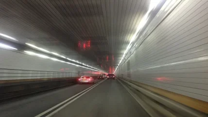
In 1927, the Holland Tunnel in New York was the first road tunnel utilising a fully transverse tunnel ventilation system.
As transverse ventilation, we consider a system with distributed fresh-air injection and distributed exhaust. Before, tunnels had been ventilated naturally by longitudinal airflow.
In the 1980s and early 90s, smoke extraction systems were still designed as section-wise distributed extraction. This was the obvious choice as the ventilation design was driven primarily by the requirements for in tunnel air quality.1 This was the case especially for long bi-directional tunnels, such as the Montblanc, Tauern, and Gotthard tunnels.
Extraction ducts were typically connected to the tunnel with small, evenly spaced open vents.2 In response to a tunnel fire, the fresh air supply was reduced while the exhaust in the fire section was maximised. In some tunnels, fresh-air supply fans were reversed to extract smoke through fresh air vents. But the tunnel fires in 1999 and 2001 indicated the limited capabilities of this concept.
In the Montblanc and Gotthard fires, there was a significant barometric pressure between the tunnel portals, causing high flow velocity in the tunnel and rapid smoke propagation. But even without meteorological pressure, the effectiveness of distributed extraction is limited. After the fires, smoke tests were performed in other tunnels. The observations quickly lead to upgrades of the ventilation systems and to the installation of smoke dampers. At the time, there was no market for this equipment. Smoke dampers had to be designed, constructed, and tested specifically for the application.
Different damper types were tested in the San Bernardino Tunnel in Switzerland.2 Dampers with sliding blades and linear actuators, single-blade dampers using a movable counterweight, and, the parallel-blade dampers that we use today, as shown in Figures 1, 3 and 4.
The change from distributed to local smoke extraction was so swift that, in 2007, a World Road Association (PIARC) report2 states: “Extraction capacity is usually concentrated to a zone smaller than the length of the duct by addition of motorized, remotely controlled dampers.” The report lists several tunnels that had then been recently equipped with smoke dampers.
In the 2011 PIARC report3 on emergency ventilation operation, it is mentioned that “Recent developments of transverse systems incorporate remotely controlled dampers enabling point smoke extraction.” In 2011, the traditional system of distributed smoke extraction has all but disappeared from design considerations for new tunnels.
EFFECTIVE?
To understand the differences between distributed and local exhaust, three simulation scenarios were performed using a 1-D software model4 to study the spread of smoke from a fire incident in a tunnel.
The tunnel in the simulation has bi-directional traffic, is 2km long, and has a moderate 1% gradient, downhill from left to right (chainage 0m – 2000m). There is no barometric pressure present. For the model, the truck fire is located at x = 1500m chainage.
Airflow is modelled at locations 100m within the tunnel from each portal. The locations are represented as u1 (closer to 0m chainage portal), and u2 (closer to the 2000m chainage portal). Positive flow is defined from left to right (i.e., with the chainage).
It takes three minutes to detect the fire and to start the smoke extraction (visible as u1 . u2). With the extraction, u1 (left portal) becomes positive and u2 (right portal) negative, indicating airflow into the tunnel from both portals. Fresh air from the portals replaces the extracted smoke volume. In each scenario, the smoke exhaust capacity is 150m3/s.
Figure 2 shows the results of the three simulation scenarios (Figure 2a-2c), represented on two graphs: on the left, the graph shows longitudinal airflow velocity versus time; and, the graph on the right shows smoke propagation along the tunnel chainage with time. On the latter graph, light grey shading indicates a potential for smoke stratification while dark grey shows smoke filling the tunnel cross-section.
In scenario a), shown in Figure 2a, the tunnel has two successive ventilation sections, each 1km long, totalling 2km. When the fire is detected, the extraction is started immediately. The extraction is equally distributed over a length of 1km, which is half of the tunnel length. In this scenario, the ventilation system is unable to limit the smoke propagation. It may slow down the smoke fronts, but after 18 minutes a major part of the tunnel is filled with smoke. As the smoke cools down, there is little chance of smoke stratification in 500m distance from the fire.
In scenario b), shown in Figure 2b, the tunnel is equipped with smoke dampers in the false ceiling for local smoke extraction. When the extraction system is started, several smoke dampers are opened, limiting the extraction section to a length of 200m at the fire.
While the same extraction capacity is applied, smoke control is significantly improved. The smoke propagation toward the left of the graph is slowed down allowing people more time to reach the emergency exits. The local extraction captures the smoke at a higher temperature, thereby limiting the buoyancy of the hot smoke and reducing the longitudinal flow in the tunnel. But such a concept is very vulnerable to external pressure from external wind or barometric pressure, or to buoyancy of hot smoke in steep tunnels.
In scenario c), the smoke is fully controlled in the extraction section. This is achieved by local extraction combined with controlled operation of jet fans in the tunnel, aiming at symmetrical flow from both sides towards the extraction section. Jet fans for flow control were introduced with the transition from distributed smoke exhaust to local smoke exhaust.
In a real tunnel, the effect of an upgrade from distributed extraction to local extraction is even more striking. A typical capacity for distributed extraction was 80m3/s per km.1 This is about half the capacity applied in scenario a). And, for such a tunnel, a typical capacity for local smoke extraction in scenario c) is 180m3/s to 200m3/s, which improves smoke control even further.
COMPLEX
While the smoke control concept of using smoke dampers and controlled jet fan operation is proven much more effective, it comes at a price.
With distributed smoke extraction, ventilation operation requires only three steps: detect the fire; assign the fire to a ventilation section (~1km in length); and, start the smoke extraction. With only three steps in the control routine, there is only a small risk that the system does not operate as intended, such as the fire might not be detected, the system could assign the wrong ventilation section to the task, or the fans might not start.
While more effective, local smoke extraction is also more complex in that the system requires more steps, as follows:
- Detect the fire
- Assign the fire to a fire section (100m length, approximately)
- Open the smoke dampers
- Start the extraction fans
- Select the airflow monitor as input for the controller
- Measure and process the airflow velocity in the tunnel
- Select and start/stop jet fans to control the airflow, And
- Repeat the last two steps, measuring and processing airflow, and starting/stopping jet fans
For the system to operate as intended, every step must be done correctly.
An availability assessment for the smoke control function must consider fire detection, control system, power supply, smoke dampers, exhaust fans, jet fans and airflow monitors. Automatic fallback solutions for failing equipment may improve the availability of the system. Indeed, maintenance requires a significant effort. I consider the airflow monitor to be the weakest spot.
A typical and probably worst-case scenario is a faulty airflow monitor feeding a wrong flow velocity to the controller. This is why sufficient redundancy must be installed. With several airflow monitors, automatic plausibility checks are possible. Faulty measurements can be identified and disregarded. Some countries define a minimum requirement of two triplets of flow monitors for any tunnel section with controlled airflow.
If powerful jet fans are installed, dynamic control requires the fans to be equipped with variable speed drives (VSD). In some countries, it has been found sufficient to have a small number of jet fans controlled by VSD. Variable speed drives usually have half the design life of a tunnel jet fan. Again, availability is a main driver for the design. High availability is achieved by sufficient redundancy and by thorough maintenance.
CONCLUSIONS
Today, distributed smoke extraction has disappeared from ventilation design considerations for new tunnel projects. Instead, smoke control by local smoke extraction is a ventilation concept proven in multiple applications, in smoke tests and in real fires.
Design requirements for the local smoke extraction concept, and the necessary technical requirements for equipment and system control are available in the technical literature, and in various national standards. Some national codes include detailed recipes for the selection of parameters for jet fan control.
And, of course, any complex safety system requires rigorous testing during commissioning and as part of regular maintenance.
Current developments aim at reducing costs, improving availability and for the specific operation of the tunnel ventilation system in combination with other safety elements, such as emergency exits and/or fixed firefighting systems (FFFS).


