The Strood and Higham tunnels were originally constructed as canal tunnels between 1821-1824, using a number of headings excavated from the tunnel portals and a number of working shafts (T&TI, March 2005). During 2000, a 12m diameter hole at the surface, tapering to a depth of 11m appeared in an apple orchard. There was no noticeable effect on the brick lined tunnel 30m below, but the assumption was that a construction shaft had collapsed. Network Rail instructed Halcrow to undertake an initial feasibility study, and then under a separate instruction within the main tunnel relining works contract, main contractor Costain, and its designer, Halcrow, were given an instruction to reinstate the ground to its original profile. This had to be within defined constraints of ensuring there was no additional load to the existing tunnel lining, and no encroachment on the tunnel profile.
Background
The tunnels were constructed using 12 known working shafts, used for material hoisting, climbing access and ventilation purposes. There may also be other shafts with uncorroborated locations, which may have been backfilled following tunnel construction. There are five shafts in the Higham tunnel. Four were filled with Wilkit foam following the recent tunnel lining works, and one was filled with foam concrete prior to undertaking the recent works. Strood tunnel has seven known shafts. S1, S2 and S3 were filled with Wilkit foam following the recent relining works during August 2004. S5, S6 and S7 were filled with foam concrete in the late 1990’s due to risks of instability. Collapse of shaft S4 was believed to be the cause of the surface settlement, and although the exact location of the shaft was not known, the frequency of the other shafts indicated that there was one in this area. However, there were also known to be a number of dissolution features in the area, along with disused flint mines.
Recovery study
The first phase of the study was to investigate the suspected shaft by 3D tomography using four bored holes on each side of the collapse to send and receive the seismic signals. The variations in seismic velocity were related to physical parameters such as density, and the area of the collapse and the tunnel clearly showed up, along with a number of other zones that showed similar seismic responses.
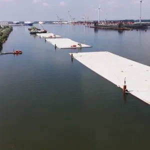
Also, data from a laser survey showed a circular shape in the tunnel crown in the soot cake covering the lining, although nothing was visible from within the tunnel by eye (figure 1). The diameter of this circular shape was 8m, far too large to be the shaft diameter, but it was considered likely that this detail, and the collapse, were caused by a shaft. However, a dissolution feature could also have been involved in the cause of the collapse.
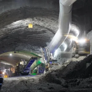
Core holes from tunnel level were taken to intercept the shaft from two sides, and to investigate one of the outlying voids (figure 2). The logs picked up brickwork on one side of the shaft, but not the other, and it was felt that the cores must have intercepted part of the collapsed brick domed cap that was assumed to be in the open shaft. The area between the brick lining and the chalk appeared to be full of low to medium density chalk fill with brick fragments, although it was uncertain if this was back fill material, or collapse material.
A third core hole did intercept some solution features, in the form of open structured chalk, with sand in-fill, but no open voids. This went some way to explaining the low velocity features shown from the tomographic survey, but didn’t discount the chance of there being open voids.
It was concluded that there really was a shaft, and the collapse had been as a result of a failure of the brick cap at the chalk rockhead. The shaft diameter was estimated to be between 4.2 and 4.9m, calculated from the volume of the surface void, although this appears larger than historical information suggests. There were dissolution features in the surrounding geology, possibly with voids, and there were likely to be voids within the collapsed material. There was also loose material between the lining extrados and the ground, again, potentially with voids.
Treatment works
A detailed review of the possible remedial works options and methodologies in relation to the Client requirements and personnel safety, resulted in a solution consisting of six main stages. The solution benefited from recent experience gained on the nearby CTRL C320 Thames Tunnel crossing, where treatment in various grades of chalk was conducted in advance of tunnel cross-passage construction. This established parameters for chalk treatment using microfine grouts.
At Strood, there was limited SI, but the chalk was known to be Grade A and the treatment was therefore designed to improve the strength of the chalk and fill any voids around the tunnel by way of pressure grouting. It was known that groundwater level was around tunnel invert level but the methods selected for treatment allowed for control of water in the event of discharge. To minimise loading to the tunnel lining the design required that the treatment was phased to provide sequential filling.
There was a requirement to maintain half tunnel access for the main tunnel relining operations, which necessitated operational flexibility for the drilling and grouting works to meet the tight programme. A Wombat rig was selected for the drilling works within the tunnel, which was operated from track level, with only man access required at the borehole entry position for which a lightweight scaffold was used.
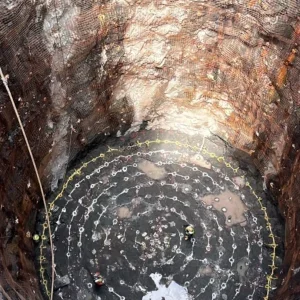
Throughout the treatment works, real time monitoring of the tunnel lining was conducted using electro-level arrays on each side of the shaft, with convergence monitoring at routine intervals to beyond the treatment zone. Trigger levels were set at 50% of permitted movement levels, but in the event no movement of concern was detected. The tunnel lining locally consisted of 450mm brickwork, which was carefully inspected before the works started, was found to be in reasonable condition and was visually monitored throughout. The staged works consisted of the following (figure 3):
Stage 1 – Install steel channels to the tunnel lining face using rock bolts through to the chalk to provide additional tunnel support during all temporary works. Four rows of 3m long bolts (64 No., 25mm diameter) were installed in 27mm cored holes.
Stage 2 – Undertake cavity contact grouting of potential voids between the tunnel walls and external geology to improve the lining capacity and to secure the shaft directly above the tunnel. Grout barriers were formed at each end of the treatment zone using a viscous grout with thixotropic stabiliser (Conbex 653) to control grout loss and allow treatment to half the tunnel at a time. Holes were cored 500mm into the chalk at 1.5m centres, and grouting conducted in four “pours” to balance loadings. A relatively viscous OPC/bentonite grout was used, with low pressures (0.35bar). An average gap of around 100mm between the lining and the ground was found at most borehole positions, and this was also treated.
Stage 3 – Undertake permeation grouting of the bottom 6m of the shaft to reduce the risk of direct load transfer to the tunnel lining. Plastic tube-a-manchettes (42mm diameter, with sleeves spaced at 330mm) were used at 1.2m centres, with grouting conducted in an upwards direction, away from the tunnel, with three phases:
Pre and post treatment sleeve water testing indicated a permeability improvement, from 10-5 to 10-7m s-1.
Further testing within this zone was conducted by dynamic probe testing which was conducted after compaction grouting to the shaft infill (Stage 5). Analysis of grout injections showed treatment volumes to be in the order of 20% of the chalk infill at the base of the shaft, which was consistent with predictions.
Stage 4 – Grout a 6m annulus of the surrounding chalk from the tunnel to increase ground stiffness and fill voids. Radial holes at 1.5m centres were drilled using water flush, with grouting conducted in 3m stages such that loading to the tunnel was evenly balanced, with pressures restricted to 5bar.
Treatment was conducted with microfine grout (Rheochem 650) using high speed colloidal grout mixers. Prior experience had demonstrated the requirement for finer cement for such treatment. In all, some 2050m3 of chalk was treated, with grout take at 2.1% of chalk volume.
Stage 5 – Fill the 11m deep and 12m diameter void at surface level with foam concrete in 5 layers. The lowest pour had a higher strength (3N/mm2) to support subsequent plant loading. The upper 2m was filled with imported chalk and used as a working platform for the subsequent compaction grouting.
Stage 6 – Compaction grouting of a 13m height of collapsed material, overlapping the Stage 2 works by 1m, to eliminate future settlement. Treatment was conducted through 7 No. cased/auger boreholes, working on a Primary/Secondary/Tertiary approach. The Primary boreholes were injected using lower pressures (0.5 bar/metre depth) to limit loading to the shaft infill. Pressures for Secondary boreholes increased to 1.0 bar/metre depth, to achieve improved penetration and consolidation of the chalk infill. The Tertiary borehole acted as a proving hole. Analysis of grout takes showed that treatment was achieved with grout consumption at 25% of the shaft volume.
Prior to compaction grouting a series of dynamic probes were conducted to verify the shaft location, to provide pre-treatment strengths, and to provide correlation with design. Following treatment, probes were taken within the compaction grouted zone and within the previously grouted Stage 2 permeation zone, demonstrating satisfactory levels of consolidation with increased probe resistance (figure 3).
Reinstatement of the surface with topsoil to a depth to match the existing area was completed slightly ahead of programme, allowing the overall Strood and Higham project to be successfully completed in January 2005. The shaft treatment works were a critical aspect of the main reinstatement project, and the project success was achieved through close technical and logistical cooperation by all parties.
Related Files
Fig 2 – Cores through shaft and dissolution feature
Fig 3 – Staged treatment and soil strength improvement