Anyone working within the tunnelling industry will know that it is somewhat of an expensive pastime, even more so when things go wrong. To prevent problems during tunnelling works, the planning of and correct establishment of a tunnelling site is as much a vital part of the tunnelling process as the actual tunnel construction itself.
As part of the tunnel planning process, ground investigation is essential. Not only does this tell the tunnel engineer what type of ground to expect to have to pass through—thereby dictating the tunnel excavation options available—it also gives the engineer the necessary information for any further forward-planning that may be necessary.
Where soft ground is present, high water table/pressure, fissured and or water-bearing or potentially unstable rock, the information provided by the ground investigation will indicate whether any form of ground pretreatment is desired or necessary to prevent problems during the tunnelling phase.
Pre-treatment regimes can normally be classified into one of three broad types, dewatering, grouting or freezing. While this list may seem relatively simple, each subdivision has its own particular set of techniques and installation options as well as each having their own peculiarities to consider when it comes to their use. We shall look at an overview of the options available from each in turn.
Dewatering
While dewatering, or ground water control as it is sometimes referred to, may sound the simplest of the techniques being discussed there are aspects of this option that do bring various complexities with them.
Dewatering in essence is the temporary reduction of pore pressures or groundwater levels to provide dry, stable and safe soil conditions in or around excavations that lay below the natural groundwater level. The technique is generally used to facilitate construction of deep excavations such as those required for basements, tunnels and other underground structures.
Depending on the depth of the excavation there are three techniques available for the control of ground water levels deepwell, ejector and wellpoint.
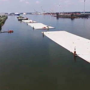
Deepwell dewatering systems generally comprise a series of bored wells designed to cover the area over which the dewatering activity is required to be effective. Each bore is fitted with a multi-stage electric submersible borehole pump.
In unstable and or granular soils wells are usually fitted with a liner and screen to provide borehole support while allowing ingress of the groundwater for extraction. Around the well liner the use of filter packs and grout seals may be required. Pumps are powered and operated from a central control cabin with the discharge water normally being collected via a ring main.
The deepwell technique is particularly suited to deeper excavations or where artesian groundwater pressures threaten ground stability during excavation and are best suited to homogeneous aquifers that extend well below the bottom of the excavation. The system is known to be a reliable one and the use of widely-spaced wells also helps to reduce access restrictions to a site to a minimum.
Deep wells can vary in diameter from 76mm to over 600mm and can be installed from as little as 6 m to hundreds of metres deep. Pumped volumes can also vary from just a few litres per minute to thousands of litres per minute.
Ejector dewatering systems (or eductor systems as they are sometimes referred to) are also used to control pore pressures and to lower groundwater levels to provide stable working conditions in excavations. Ejector systems are designed to extract groundwater and generate a high vacuum at the base of well bores at depths of up to 50m using bore diameters of as little as 50mm. The use of the vacuum drainage technique can dramatically improve the stability of silty fine sands and laminated silts and clays by controlling excess pore pressures within the ground structure. Ejectors are typically used where the groundwater must be lowered more than 4.5m and the soil is of low hydraulic conductivity so that vacuum application is of benefit to improve soil drainage. Since such systems are not limited in suction lift and generally have a lower unit cost than deep wells, ejectors are well suited for deep excavations in stratified soils where close spacing is required.
Supply pumps at ground level feed high-pressure water to the ejector nozzle and venturi, which is located at the base of each well. The flow of water through the nozzle generates the vacuum in the well and draws in groundwater from the surrounding soil, which is then extracted by the pumping system.
Wellpoint systems are more suited to the dewatering of shallower structures such as foundations and trench works.
A wellpoint system comprises a closely spaced series of small-diameter shallow bore wells that are connected to a common headermain. The system is driven by the use of a high-efficiency vacuum dewatering pump. For drawdowns in excess of 6m further stages of wellpoints are required, installed at successively lower levels as excavation proceeds.
Rapid and cost-effective wellpoint installation may be achieved in sandy soils by jetting using high-pressure water; drilling installation may be preferred in coarse or cohesive soils.
Sebastian Fisher, design manager of WJ Groundwater, says “groundwater control as a technique is designed to remove groundwater or reduce pore water pressure to allow stabilisation of an excavation/Slope to allow construction in the dry. This means there needs to be a balance between a well-engineered scheme being put into place at the same time as making the technique cost effective so to be considered as an alternative to other stabilisation techniques. Groundwater control therefore adds another dimension to the geotechnical/civil engineering community with respect to ground stabilisation.”
Grouting
Where grouting techniques can be used for the stabilisation of ground there are several techniques available to the engineer, some well-known and others not so well, but none the less available.
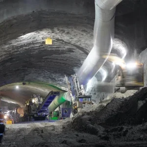
Grouting techniques as with other systems tend to rely on the use of boreholes into the unstable ground matrix that requires stabilisation. The grout is then pumped into the ground through the boreholes usually under pressure to force the grout mix through the borehole wall into the soil or rock matrix. Grouting can used to prevent water flow and to add structure to and unstable ground matrix.
The range of techniques available includes:
• Cement grouting
• Jet grouting
• Chemical grouting
• Compaction grouting
• Asphalt grouting
• Low-Mobility grouting
The conventional grouting technique is the use of Cementitious grouts as this option tends to be the least costly method. Cementitious grouts usually comprise suspensions of material such as cement/water or more stable cement/clay/water and admixture mixes. Other suspensions can include liquids, pure solutions (resins), colloidal solutions (gels) and emulsions.
Jet grouting is a construction process using a high kinetic energy jet of fluid to breakup and loosen the ground, and mix it with a thin slurry. It is not really a true grouting technique but is rather a hydrodynamic mix-in-place technique producing a soil-cement material. The technique has three physical processes, which operate singly or in combination including:
• The very high speed jet loosens the soil
• The jetting fluid washes some of the soil to the surface
• The slurry adds a binder to the soil mix
A jet grout sequence normally comprises the boring of the grout hole followed by the introduction of the high-pressure grout fluid through a specially-designed nozzle on the end of the drill string at the bottom of the bore. The nozzle is then raised as the drill string is rotated causing the soil breakdown to occur. The fluid then mixes with the soils to settle back into the bore as the nozzle passes so creating the cementitious mix required for ground stabilisation. The fluids used can comprise various compositions including: single (cement only) fluid, double (cement with air) or triple (cement with air and water) combinations.
Chemical grouting uses a very low-viscosity chemical grout (polyurethane based usually) that is pumped into granular soil to improve the strength and rigidity of the soil to limit ground movement during construction. Chemical grouting is used extensively to aid soft ground tunneling and to control groundwater intrusion. As a remedial tool, chemical grouting is effective in waterproofing leaking subterranean structures. A key advantage of chemical grouting is its ability to introduce grout into soil pores without any essential change in the original soil volume and structure, thus changing the support capability of granular soils without disturbing them.
From increasing the bearing capacity of soils under slabs and spread footings, to reducing liquefaction potential, arresting foundation settlement, lifting and leveling structures, providing pre-construction site improvement, and controlling settlement over tunnels or sinkholes, compaction grouting is a technique that can be used. Compaction grouting is a method of ground treatment that involves injecting a very stiff homogeneous grout mix, under relatively high-pressures, and at low injection rates into subsurface locations in pre-designed patterns in order to displace and compact soils. The injected grout pushes the soils to the side as it forms a grout column or bulb around the injection point.
Two other less commonly known grouting techniques also exist which are those of asphalt grouting and low-mobility grouting (LMG). Asphalt grouting has been used to plug leaks in cofferdams and in natural rock foundations. Asphalt is a brown-to-black bituminous substance belonging to a group of solid or semisolid hydrocarbons. When it is used for grouting, it is generally heated to 200° or 230°C before injection. Additionally, asphalt emulsions may also be used for grouting with these being applied cold. In the emulsion the asphalt is dispersed in colloidal form in water. After injection, the emulsion is broken so that the asphalt can coagulate to form an effective grout using special chemicals injected with the emulsion for this purpose.
LMG is used in situations where the grout mix needs to have a very limited ability to travel from its point of injection. These situations are common for grouting abandoned mines, karst solution cavities, and for water cutoff projects (similar to asphalt grouting for water cutoffs). The means and methods for LMG are very similar to compaction grouting, which by some is seen as a form of LMG with the exception that a slightly higher slump range is used on the grout mixes.
Many of the grouting processes covered above also now use computer-aided control systems to monitor and control the pumping systems that place the grout, helping to eliminate the potential for any human error in the grout mix, pumping pressure or placement.
Freezing
When it comes to freezing ground for the purpose of stabilisation and control, there are two main methods employed to create the supportive ICE ‘block’. These are known as mass and peripheral freezing. Both systems require the installation of a series of boreholes through the ground structures that are the cause of concern. The bore hole pattern must be of a range and distribution that the complete proposed excavation region in the ground is covered, probably with an oversized safety margin to allow for any unexpected occurrences.
The ethos behind freezing techniques is that once the bores are installed and the cooling tubes and refrigeration plant are in place, the circulating coolant lowers the ground temperature to the point where water and or moisture in the ground turns to ice. Continuing with the cooling creates a halo of ice around each individual bore. As this halo grows it overlaps with adjacent halos from nearby bores forming an ice block. Once all the halos interlink the ground is frozen solid.
The first technique, mass freezing, is the probably the simplest. This technique is used in certain circumstances where it may be desirable to freeze massive volumes of soil to facilitate excavation within the frozen stabilized ground. These types of freezes are less common than peripheral freezes.
Mass freezing may be justified where:
• Ground control in difficult subsurface conditions is crucial to the success of a project.
• No geological cut-off is present within reasonable depth below subgrade at a given location, which means the use of ground freezing may necessitate a mass freeze to artificially create a bottom seal that local geology fails to provide.
• There is concern about the overall safety of the operation.
The problem with mass freezing of course is that ice is not a soft substance so to create any tunnel or other underground structure would entail mining through the now very hard ground.
This is where peripheral freezing comes into its own. The general intent of peripheral freezing is to minimise the amount of frozen ground to be excavated. The boreholes used in the design of a peripheral freeze are such that the halos between the bores form a frozen wall, of the appropriate thickness and strength that is created, for the most part, outside of the excavation area which but extends some distance inside the future excavation surface so that any freshly exposed face remains stable. Peripheral freezes must be formed with sufficiently watertight bases to ensure that excessive groundwater leakage from outside the frozen region doesn’t develop as an upward flow into the unfrozen ground inside the frozen barrier. In essence the bore for a peripheral freeze should terminate in an impermeable layer in the ground strata.
Since frozen ground can be created with any freeze pipe orientation, ground freezing can be a very effective stabilisation tool for tunnelling operations. Vertical freeze pipes can be installed to create a frozen arch through which tunnelling can proceed. The sides of the arch extend to an underlying impermeable cut-off horizon below the tunnel invert, while short pipes are used to freeze above the tunnel crown. Vertical pipe installation can also be used to create a full face tunnel freeze.
Other typical situations in which peripheral freezes are suitable include:
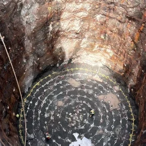
• Shafts
• Large circular, open excavations
• Small connections between structures.
While the descriptions given above relate to using the technologies from surface down to the tunnel horizon, most if not all could be used from within the tunnel if absolutely necessary. However, the interruption to the tunnel’s advance, and the potentially huge cost of installing such systems underground would tend to make such a move prohibitive. While this may not always be the case, the general consensus is that if the ground ahead of the tunnel face is likely to need pre-treatment it is best to look at doing it ahead of the tunnel face from surface if not before tunnelling starts.
A deep well instalation by WJ Groundwater A Unigrout unit injecting grout into the tunnel face A Keller grouting rig Ground freezing on San Diego South Bay Ocean Outfall project