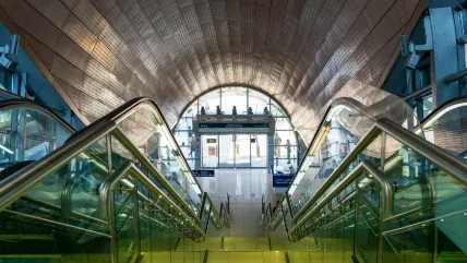
The Client for all works is the Dubai Roads & Transport authority (RTA) for which two lines of the metro system are currently under construction totalling some 70km route length, of which 13km will be in tunnel, beneath central Dubai and the Dubai Creek.
The 52.1km long Red Line will have 29 stations, four of which will be underground. It will run from Rashidiva to Jebel Ali, on a north/south axis through the main thoroughfares of Dubai. The 17.6km long Green Line will have 14 stations of which six will be underground, and will have two interchange stations with the Red Line at Burjuman and Union Square.
Plans are already in place to extend the network by four new lines, a Purple Line (49km), a Blue Line (50km) and Palm Deira Yellow and Black Lines (26.5km), with extensions to the majority of lines planned.
Detailed design: This section on the detailed design was presented by Paul Groves, Atkins Tunnels Design Package Manager, who explained that Atkins was appointed as detailed designer by the design and construct civil contractor, JTM JV, the civil partner in the single contracting organisation DURL CONSORTIUM. The rail systems partner was Mitsubishi Corporation. The Engineer to the Contract was Systra/Parsons JV.
The Design & Construct Contract document contained a Reference Design (DCP1) produced by Systra and this had been developed by Atkins through the following project detailed design stages:
- DCP2: Preliminary design
- DCP3: Detailed design (fit to commence construction)
- DCP4: Fully Approved Design
The detailed designer also had a continuing involvement during the construction phase in a support role.
Investigations were developed from Pre-Tender Site Investigation (SI) data by way of a geological desk study. Further SI for the detailed design comprised boreholes, in-situ tests within boreholes, lab testing, pumping trials and geophysical and bathymetrical surveys. During construction, further boreholes, trials and tests, foundation inspections and mapping of exposures were carried out.
Ground comprised loose to medium dense, high permeability marine sand, cemented sand Sabkha deposits with some hard concretions and voids, underlain by calcareous sandstone interbedded with cemented or uncemented sands (hence more of a soil than a rock material), underlain by interbedded
gypsiferous sandstone and then siltstone. A high water table existed throughout the scheme, with the groundwater being hyper-saline (<1.08T/m3). Both the ground and the groundwater were described as extremely aggressive.
(Longitudinal sections of both the Red and Green Line tunnels are shown in Figure 1. Escape shafts are located as off line annexes at low points, combining sump pump discharge with ventilation and escape functions. A cross section of the 8.5m i.d. twin track tunnel is shown in Figure 2. The 400mm thick tapered rings were 1.5m long, each comprising seven segments plus a key. Segment accessories comprised 25mm spear bolts, EPDM gaskets & hydrophilic strips, cast-in threaded inserts and lifting eyes/grouting valves. A linear heat detector will be installed in the crown along the full length of the completed tunnels.
The structural design of the segmental lining was to BS 8110 and included for ground, water and surcharge loads, a seismic loading (0.15g), jacking loads from propulsion rams, and effects of ring building, grouting and handling.
The lining was fire rated to four hours (BS 8110) in fulfilment of the Contract. In order to provide the 100-year design life durability, the concrete mix used in all segmental linings was a blended C50 concrete mix, designed for a maximum crack width of 0.2mm, with 50mm cover to rebar on the extrados.
A flexible epoxy coating was applied to external surfaces.
Structural damage risk mitigation
Buildings & structures were described as typically low-rise or less than eight storeys, and were mostly RC framed structures on rafts or shallow footings. There were however some piled structures including some structures under construction, such as the deep basement Al Ghurair Centre, piled to below tunnel horizon.
The DNATA Building (Emirates Airline Centre) was described as being at greatest risk. This was a significant piled frame structure directly over the tunnel. The pile length was unknown, therefore an investigation of pile length was carried out by seismic logging and magnetic logging. It was found that pile toes were some 5m above the tunnel. The design approach adopted was to evaluate tunnel-pile interaction analysis to determine tolerable volume loss, from which it was found to be below 0.5%. It was considered preferable to achieve this using TBM operational pressures rather than intrusive mitigation.
The project adopted a risk based approach to structure damage risk mitigation. A risk assessment was conducted for all structures based on a volume loss of 1%, using the method postulated by Mair et al (1996). All piled structures were analysed using finite element methods. Additional measures were planned for structures considered to be at "slight or greater" risk. Back-analysis of monitoring field data from the initial Red Line drive was used to inform the process, with the result that the additional measures in terms of close monitoring and precise adjustments of face pressure and annulus grout pressure were sufficient controls and no further actions at the surface proved necessary. Such special measures were envisaged to be beneath the DNATA building on the Red Line only and not on the Green Line.
The project Environmental Impact Assessment identified two petrol stations at risk from settlement damage. The alignment passed directly under the storage tanks of one petrol station and passed close to another. Monitoring of ground water and of excavated fill was undertaken to check for tank leakage as the TBM passed, ensuring compliance with NFPA requirements.
TBM selection
With the intention of limiting settlement, the calculated face pressure was based on limit equilibrium of the soil wedge, with assumptions on chamber pressure based on Anagnostou & Kovari (1996). The annulus grout pressure was based on an analytical stability calculation for cohesionless soils, according to Atkinson & Potts (1977). Because there was no precedent experience of TBM tunnelling in Dubai, a trial initial drive was deemed important for validation. As a risk mitigation measure, a second screw conveyor was added to the back up, to ensure maintenance of face pressures in the cohesionless soils. Results from the initial and heavily instrumented Red Line trial drive were presented. Typical volume losses were around 0.3% with a maximum of 0.65% which correlated with some localised tailskin grout losses that was subsequently repaired.
The Dubai ground conditions (much of which is cohesionless with a high percentage particle size around 0.1mm) were described as suitable for either an EPBM or Slurry Machine (STM). Japanese project experience between 1997 and 2006 of 322 STM projects and 932 EPBM projects was investigated by JTM.
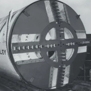
It was decided that EPBMs would be used, with spoil conditioning using rheological foam injected at the face. This reduced the slump of the spoil sufficiently for a pressure gradient to be maintained along the screw conveyor and for the resultant spoil to be handled by conveyor and placed in a muckpile. Three 9.56m diameter Mitsubishi EPBMs were deployed on the project in ten separate drives. Four of the drives radiated out from Union Square, while two further drives on the Green Line ‘loop’ were driven from Palm Deira and Al Ras.
The cutter heads were fitted with shell and scraper cutter tools projecting from the cutter head at two heights, with scraper bit shell bits at 145mm and shell bits at 105mm. Cutter tools were reported to be in good condition after the drives, thought to be a result of the sandstones not containing appreciable quartz cementation and in conjunction with the use of foam injection, did not prove to be particularly abrasive.
Muck removal was by conveyor with vertical conveyors in drive shafts. A combination of horizontal and vertical conveyor cassettes (one each in the tunnel and the shaft) gave a capacity of 200m without interrupting the drive. Average progress was 10 Rings (15m/day) with the maximum production in any 24 hour period being 21 Rings (31.5m).
Extensive data management systems were used, and the three TBM drive sites were connected to a common data system through the Internet. Real time monitoring, relayed to the surface site office included drive data, muck sensor control PC (linked with belt weigher), face & grout pressures, gas detection, camera images and total station data. The TBM data collection system was updated every minute.
Building settlement monitoring data was emailed to site offices, supplemented by automatically generated SMS messages to engineers’ mobile phones if alarm values were triggered.
TBM launching
TBMs were launched from steel thrust frames through soft eyes in the station box diaphragm walls, initially with the aid of pre launch ground treatment. Sealing arrangements included launching eye, comprising a rubber seal with sprung steel plates. Leakage was negligible and it was subsequently decided to launch the other drives without further ground treatment.
TBM arrival at the end of each drive was though a partially dewatered zone created by a slurry wall parallel to and offset some 10m from the station box headwall, with pumping wells in the ‘protected’ zone.
The drive sequences were such that TBMs needed to be dragged/walked through four stations on steel rails cast into the base slab concrete – the fourth was ongoing at the time of the talk.
All grouting was through ports at the rear of the tailskin with a 2 component system, Part A comprising a cement bentonite grout, and Part B being sodium silicate. This mix set to a gel some 20 seconds after injection mixing. A dry tunnel was achieved through a good ring build and the presence of this primary grouting, and no further grouting through the lining proved necessary.
A casting yard was set up for the project, casting in high ambient temperatures well over 40°C, for many months each year. Two mix designs were used according to temperature and included silica fume.
Two production lines had been established, casting around 12 x 1.5m long rings (96 segments) per day. However, an early start to the Green Line had required a third production line, increasing output to 128 segments per day. Segment casting was due to finish in November 2008.
Safety & environmental
Accidents are reportable where the worker is off work for three days or more, not including the accident day. The target for the Metro was set at no more than 1 reportable accident per million man-hours worked. Approximately 113 million man-hours had been worked on the project, for which there had been 133 reportable accidents. The accident frequency rate (AFR) was stated to be 1.18.
Questions & Answers
Q: Mike McConnell (retired) noted that fire evacuation route for rail passengers was along a 0.61m wide raised walkway at about vehicle floor level, with evacuation shafts at 1.6km centres. He asked how long the evacuation of a train load of passengers was expected to take.
A: Paul Groves replied that maximum escape length from the train to a point of safety, either station or escape shaft, was 800m. Evacuation of a train load of passengers to a point of safety was estimated to take up to 24 minutes. He also noted that in his view, and probably that of most British tunnel engineers, train evacuation in a twin track tunnel was harder to achieve than in a single track tunnel arrangement. Nevertheless, the design has been developed to comply with the contract specifications and NFPA-130/ITI-98300 and was based on the contract reference design, produced by Systra and based on established French practice, which included the minimum tunnel diameter, twin railway tracks and elevated walkways.
Q: Gerard Skalla (Dr Sauer Company) commented that a grouted solution had been originally planned for ground stabilisation and treatment for breakouts.
A: Initial results of permeation grouting with silicates had proved that the grout was not giving the expected strength gain/permeability reduction, possibly because of the inherent salinity of the marine based deposits. Therefore, as a matter of expediency, slurry cut-off walls and deep pumping had generally been chosen instead.
Q: Andy Fletcher (Crossrail) enquired about community relations and, in particular, the complexities of obtaining the necessary approvals from the authorities and land purchase.
A: Paul Groves explained that the status quo in Dubai was such that due process for project authorisation was generally more straightforward than in other countries.
Q: Bob Goodfellow (Black & Veatch Ltd) asked about the numbers and locations of rail crossovers.
A: Paul Groves explained that there was a Red to Green Line crossover within Union Square Station and several track crossovers inside the tunnels, but since all running tunnels were twin track, no change in lining geometry was required for track crossings, which could therefore be located on straight tunnel sections wherever required.
Q: Martin Knights, ITA President, (Jacobs Engineering) asked a three part question regarding the cost of the project, the decision not to use fibre reinforcement in tunnel linings, and whether the participating companies were in a full joint venture.
A: Answering the first of these, Nakayama san explained that the project was unfinished, so the outturn cost was not yet known.
The second and thirds points were answered by Paul Groves who explained that steel bar reinforcement had been the contractor’s preference and that the tunnel constructor JTM was a full joint venture.
Rapporteur: John Scholey


