Home to the Steelers football franchise, it goes without saying the history of Pittsburgh is interwoven with that of the steel industry. Over the past 30 years, this symbiotic relationship has been regenerated. People who have moved into the suburbs now require public transportation to take them back into the central area, a city triangle, formed by three rivers—the Alleghany and Monongahela Rivers, which join to form the Ohio River.
The USD 435M Pittsburgh North Shore Connector project joins the redeveloped North Shore industrial area with the existing Gateway Station in the city central triangle, passing under the Allegheny. The line travels close to two stadiums—home of the Pittsburgh Pirates and Heinz Field where the Steelers play—as well as other sensitive structures, with the corner of one sport stadium car park forming the main construction site, limited to about 2,000sqm.
The project owner is the Port Authority of Allegheny County, and the construction manager is Trigold, a consortium of HDR Engineering, Jacobs Engineering and Kwame. The client designer is AECOM, and the main contractor is North Shore Constructors (Obayashi Corporation/ Trumbull Corporation). The design contract was awarded in 2002 with the construction contract awarded mid 2006. Tunnel construction was completed in April of last year. The Port Authority expects to start service on the line in spring 2012.
The 800m long twin bore tunnel alignment and access shafts were constructed through a combination of fill going back to colonial times, Alluvium deposits, permeable half gravel and half sand fluvioglacial material with possible boulders towards the base of the formation, and rock. The rock consisted of Pennsylvanian coal measure type rock— sandstones, siltstones, claystones. Shales and coal seams—with strengths ranging from just over 1MPa to over 80MPa.
Challenging alignment
The alignment presented some particular challenges of shallow tunnelling under the river with only one diameter cover, constraints between historic piled structures and the need to tie into the existing system, resulting in a 1m wide soil column between the two bores. Vertically the alignment followed a maximum 8 per cent gradient with minimum curve radii of 180m.
Where the alignment was constrained, the narrow central pillar stability was checked by two dimensional finite element analysis with a defined limiting volume loss of one per cent to safeguard the buildings. Ground treatment using 2m diameter jet grouting columns was required for a distance of approximately 14m over the first tunnel and for about a 92m length of the second tunnel. There was also a contingency measure to use internal bracing within the first tunnel covering a 45m length at any one time.
This bracing consisted of a steel rectangular frame erected at 1.2m centers over a total length of approximately 92m, using a rolling system of dismantling and advancing the frames, aligned with the adjacent tunnel progress.
The jet grouting covered only about 75 per cent of the total ground treatment volume rather than using full-face coverage following a value engineering exercise. There was less concern about water cut off, and the design was more concerned with ground stabilization. The grouting was targeted to achieve 1MP matrix strength, but this did make it difficult to sample, with a weak matrix of grout and gravel. Down the hole, cameras were used to look at the continuity as well as rotosonic drilling and taking larger samples that were less likely to be severely disturbed. The size of the jet grouted column was eventually demonstrated by geophysical means of examining changing electrical characteristics of the jet grouted material, which replaced sampling methods.
Support and waterproofing
The tunnel support consisted of a prescribed lining containing a primary lining, waterproof membrane and a cast in-situ secondary lining. Space proofing, including the defined vehicle envelope, emergency access down one side, overhead catenaries, signals, track and drainage plus secondary lining, resulted in primary segmental lining with an internal diameter of 6.1m.
Full three-dimensional finite element analysis was undertaken, taking account of ring roll and the joint arrangement, with prescriptive loadings including derailment of vehicles and explosion loading (1,000kN/m2) applied to the internal lining. A sunken vessel load (100kN/m2) under the river was also applied due to the low cover, and a design flood level set at over 6.5m above the top of river level, which might appear high but historical data showed flooding up to the 1st floor of adjacent buildings (3.65m above street level).
The bolted and gasketed reinforced precast concrete segmental lining was originally designed with seven plates and a key, 275mm thick and 1.2m wide. Two ring types were used with differing tapers of 40mm and 60mm. The contractor offered a value engineering change to the design to six plates plus a key in order to improve on ring build time in the tunnelling cycle, and the design change was accepted. The rings were produced by Technopref through a local precast concrete company (A C Miller), and CBE molds using a static casting system. A five-day secondary cure was specified to attain the design 55MPA concrete strength at 28 days.
The cast in place internal lining was designed as a 125mm thick fiber reinforced section, with a geotextile and waterproof membrane between the primary segmental and in-situ secondary lining—giving a finished internal diameter of 5.8m. Water bars were specified in the membrane to isolate bays into 6m long zones in case of any leaks. The need for the secondary lining was left for discussion as a VE opportunity with the contractor when appointed, and was eventually omitted from the works, which also provided a larger envelope in the completed tunnel.
The contractor had the option to use EPB or slurry face support technology on the TBM, and chose a Herrenknecht slurry mixshield with working pressure up to 3bar, 6.93m outside diameter, 8.26m long and weighing 485t. The TBM was provided with a counter rotating head (0-2.7rpm) variable frequency drive, with 27, 17inch twin cutters and a rock crusher.
The slurry separation plant was located next to the main working site and contained 10 cyclones of 250mm and 20 cyclones of 75mm with two centrifuges capable of handling 15m3/hr of slurry.
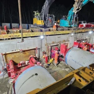
The TBM was built at the surface then lifted, transported over the shaft and lowered it down to launch leve by a gantryl—a journey of about 18 hours. The single machine was driven one way and it was anticipated that the contractor would then remove it and take it back to the same launch point. The contractor decided to turn the machine around at the reception pit in a very constrained space using a combination of rams and rollers. It was first turned 180 degrees and then translated across the shaft. The thrust frame was erected and the TBM re-launched using temporary power/hydraulics and temporary backup for a distance of 45m. At this point the full back-up was moved around to the second tunnel to be launched. The average advance rate was 9.7m/day for the first drive and 10.2m/day for the second, with a maximum advance recorded of 19.5m/day.
Steady ground
Ground movement control was an important aspect of the project, and during design and assessment of infrastructure affected by tunnelling, ground loss was specified at 1.5 per cent in soil, and 1 per cent through the rock, which was slightly higher than might normally be expected due to concern over the effect of the mixed face conditions to be experienced by the TBM. Empirical and finite element settlement assessments were undertaken leading to estimates of 20-65mm settlement along the tunnel centerline route and 12-20mm at building foundation lines.
Techniques used to control and limit ground movements included ground improvement (compensation grouting and jet grouting), with the objective to cut ground movement in half. Face loss was actually kept to between one-third and three-quarters of the design basis value in soil (1.5 per cent), while in jet grouted areas, settlement was about half that of non-treated areas.
Techniques were chosen based upon local requirements. For example compensation grouting was used successfully in close proximity to a cooling water well where it was considered that jet grouting would render the well unusable by completely blocking the local strata. At some critical locations diaphragm cut-off walls were used, and post tensioning beams and underpinning were used at the elevated highway structures in addition to some pile cutting and load transfer.
Where the tunnel passed under the south river walls ground movements were specified to be limited to 25mm. The wall consisted of pile support of unknown depth, which possibly extended down to tunnel level.
The design assumed that the piles would be removed and jet grouting used to support the wall, but it was confirmed during extraction that the piles were 2 to 3m above the tunnel crown, and the remaining piles were left in place. There was also concern at the north river wall about the toe level of the steel piles, and the contractor was considering stopping the TBM at that point.
This led to a more detailed investigation using magnetic geophysical testing to supplement the angle probing undertaken during the design. This demonstrated that the clearance was closer to 100mm than the originally determined 1m, but to a tolerance of +/-450mm. The timber piles behind the sheet piled wall were removed to check their depth and it was noted that the steel toe caps had corroded and that the length was not a concern for TBM advance, so construction continued with no delay to the TBM.
Monitoring progress
The instrumentation and monitoring (I&M) strategy was based on a philosophy of installing I&M early to give good baseline readings which, from experience, makes interpretation easier and enhances the ability to distinguish environmental effects from real tunnel induced movement. Continual feedback of data was used to provide the information for evaluating and controlling construction, and a Green-Yellow-Red trigger level warning system was adopted.
Generally, green represented less than threshold levels, yellow between threshold and a limiting value, while red triggers were hit when greater than limiting values were achieved. Generally vertical movement data was used due to the ease of collection, use and understanding, although other instrumentation and results were available. Monitoring frequency was adjusted to suit the construction activities in the area, and response plans put in place to react to specific trigger levels.
Management of third party agreements and site access for installation and reading of instrumentation was a particular problem on the project, with property ownership changing and new owners reluctant to follow previous agreements. Although these agreements were technically enforceable under the law, owners could still make life difficult for the team and use up valuable staff time in resolving the issues.
Figure 1; The alignment and other Pittsburgh routes Figure 2; The tunnel has shallow cover, just one diameter under the river The tunnel has a precast concrete segmental lining One of the twin bore tunnels with the segmental lining View of the tunnels from the reception pit The TBM breaking through at the reception pit Surface level work The alignment’s proximity to the Pirate’s stadium