To most engineers involved in civil tunnelling a shaft 30m deep is worthy of special consideration. A shaft 100m deep is exceptional. When Mark Kirkbride spoke of shafts 3000m deep, there was an audible gasp of amazement in the audience. Perhaps the gasp came mostly from the British Tunnelling Society – not the Institution of Mining and Metallurgy. IMM Members are more often involved in the procurement, planning and execution of these colossally deep shafts for mining clients. Exploitation of ever-deeper mineral reserves is the driver for these frontier-of-technique projects. Cementation Skanska are constructing 3000m+ deep shafts in South Africa and Canada. The presentation covered examples from both locations.
Planning Deep Shafts
The South Deeps shaft in South Africa, at 3003m depth and 9m in diameter, is the deepest Cementation Skanska has constructed and is the deepest single lift shaft in the world. However they expect to be going beyond 3000m in the foreseeable future. The general sequence of construction for such a shaft is as follows:
- Pre-sink: sink the shaft from ground level to about 30m;
- install headgear and winder;
- construct ventilation drift and install ventilation;
- construct and install shaft-sinking stage;
- drill and blast excavation/mucking;
- shaft lining;
- equipping: installation of permanent winding equipment
The pre-sink or foreshaft construction is typically around 30m deep. This is the surface anchor of the shaft. Often constructed in poor ground, it is designed with heavily reinforced concrete. It has to withstand the temporary loading from the shaft construction activities and also the long-term loads from the winding equipment.
The headgear can consist of reinforced concrete towers to support the sheave wheels and ropes, or steel towers. Winders are housed at the side of the headgear. The ropes are often arranged so that two kibbles are in operation, one ascending and the other descending at any given time. This keeps the headgear and winders optimally balanced. The kibbles travel at up to 16m/s with planned deceleration at the top and bottom of their journeys. The rope arrangement and geometry of the headgear allows for easy tipping straight into a bunker adjacent to the headgear and a swift descent back down the shaft.
The winders for the Selby Coalfield development in the 1980s were typically 600-1250hp. The modern ultra-deep shafts have winders of up to 11,300hp. Irregularities in the lie of ropes as they travel across the winding drum have been caused by their weight, length and harmonic behaviour. A mix of right-hand and left-hand lay ropes has helped solve some of the problems. But the behaviour and wear/crushing of the ropes has been the most significant factor in achieving the required progress at these sorts of depth.
Main shaft-sinking operations
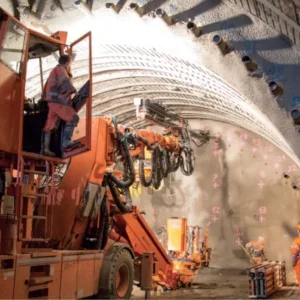
The shaft is constructed by drill and blast in the shaft sump. Above this a shaft-sinking stage is hung in the shaft on ropes from the surface. The shaft lining is constructed from the decks or floors on this moving scaffold. It consists of a fabricated metal working area containing five decks for work access. In the centre it has openings that allow the kibbles to pass through for mucking from the shaft sump. The underside of the sinking stage has a retractable multi-boom drilling jumbo for drilling 3.5-4m rounds and a suspended backacter or cactus-grab for mucking into the kibbles. In the past mucking has been effected with an Eimco loader and up to 30 men in the shaft-bottom.
Safety and economy has driven the move towards greater mechanisation, reducing the numbers of men and moving equipment at the base of the shaft. Man access is via the kibble, which passes through the stage, dropping men at the deck they need to work on. The weight of the stage is around 130t. The drilling jumbo is either withdrawn into the stage, or wound to surface when not in use. But when required it extends to the shaft floor and drills the round. The position of the holes is very important, with the perimeter often consisting of closely drilled holes for smooth-blasting, the general arrangement of other holes and a larger diameter relief hole in the centre. At South Deeps 150 perimeter holes were required per round, these were drilled to a depth of 6m. Firing patterns have been reviewed. In fact half face excavation has been useful in speeding up the cycle time. The longest activity in the cycle is mucking out, which is followed by charging the holes. The kibble can have up to a 16t payload, though large winders can lift 21t. All winding systems are monitored to prevent overloading.
The construction of the permanent shaft lining takes place from the stage. Rockbolts and temporary support are installed from the shaft floor. As the stage follows the excavation down the shaft the bottom shutter kerb ring is fixed in position using high tensile steel (macalloy bar) hanging rods, fixed onto rods within the previous pour. The lining is typically poured in 5-6m lifts. The shutters are fixed to the kerb ring and positioned, each being a 1m ring, which are placed with a typical accuracy of ± 3mm. Inserts, cable brackets and pipes are cast into this using cut-outs. 6 rings would be a normal pour. A typical pour would be 120-200m3 with concrete batched at 100m3/hour. This is delivered by skip or pipeline and remixed at the stage. The remixed concrete is placed at two points simultaneously to balance the forces. Equipping the shaft is the final stage. Whatever the requirement, equipment is made in modular units. This can be just for construction or it can be complicated, for example if Clients’ wish to mine simultaneously with shaft extension or construction. This is the case at Kidd Creek, where the shaft has to be segregated for construction and mining activities. Fabrication and installation are executed typically to ±3mm.
South Deeps and Kidd Creek
South Deeps shaft is thought to be the world’s deepest single shaft from surface to bottom. The main shaft is 3003m deep, the ventilation shaft is 2940m deep. The foreshaft is 22m deep with a concrete slip-formed tower 104m high. A 400t crane was needed to lift the sheave wheels into place. A 22t drilling jumbo was used to drill the rounds with a central down-hole hammer for the relief hole.
The winder raises the kibbles at 15m/s. An important factor in the design is acceleration and deceleration at each end of the winding cycle. The stage ropes are 4 falls of 43mm diameter rope carrying the 130t stage. The concrete lining is 20KN/mm2 mass poured. Due to the extreme depth and rope lengths there have been a number of technical challenges with the winding ropes on this shaft. The ropes were high tensile galvanised right-hand lay. Because of a number of factors, including the weight of the rope, the tension created by the winding equipment, rope layering on the drums and rope fleet angles, there were front-end waviness problems, resulting in broken strands and accelerated rope wear. Different arrangements were tried out with the winding systems and rope storage reelers in an attempt to reduce the tension and crushing forces on the ropes with some success. Monitoring of the ropes was one of the biggest problems on this project. In fact rope technology is viewed as the key to extending the practicalities of deeper shaft construction.
At such depths rockbursts are a big problem accounting for 50% of deaths on sites. The temporary and permanent linings are designed to withstand this. Ground treatment was required in areas of the shaft with poor rock quality and water inflows. Here 30m long grout holes were drilled for the injections. The phases of grouting overlapped in depth by at least 5m. The South Deeps shaft suffered water problems at around 500m depth. An inrush of 590 gallons/minute flooded the shaft. Pumping kept the water as close to the shaft floor as possible, whilst draught tubes and additional pumps were installed within a gravel. Then keeping the pumps running, concrete was poured over a crushed stone layer on the shaft floor. Grout tubes were drilled through the concrete plug into the rock and used to seal the water source.
Anisotropic in-situ stress presented problems in areas that had already been mined. A 300m distressed zoned was traversed where existing mine workings intersected the new shaft construction. This was dealt with by using 6m ground anchors and fibre-reinforced shotcrete to mine through this area. The final lining was ‘hung’ over that distance.
Kidd Creek is a sub-surface shaft extending from 1200m to beyond 3000m below surface. The entire shaft-sinking infrastructure is underground and shaft access to this area is in continuous use for mining. Logistics and supply are a major issue during construction. Apart from this, a 60m shear zone presents engineering challenges. A novel approach has been utilised by filling the void with concrete and then raise boring a pilot hole through this zone, followed by sinking the shaft using the pilot hole.
Kirkbride ended by speculating on future developments. He expected seismic tomography to become more refined and more widely used tool to investigate geological features and rock mass quality in the ground ahead of excavations. Investment in rope technology was another fruitful area for research and development. If mine owners want to exploit even deeper mineral reserves he was confident that funds would be available to develop the required technology to increase shaft depths beyond the 3000m mark.
Related Files
Figure 1: Shaft-sinking headgear
Figure 2: shaft-sinking stage