The John Hart Hydroelectric station has been operating since 1947 and an upgrade to bring it in line with modern standards is underway, at a cost of USD 1bn. The project is located on Vancouver Island in Campbell River, British Columbia. The decision to go underground was to get a more reliable, seismically and environmental friendly facility, in addition to providing an increased capacity of 132MW.
The Frontier-Kemper/ASL joint venture will carry out the underground works.
The involved parties are:
- Client: British Columbia Hydro and Power Authority (BC Hydro);
- Build Consortium: InPower BC General Partnership;
- Design-Build contractor: SNC-Lavalin Incorporated;
- Civil Contractor: ASL JV— a joint venture between Aecon Constructors, a division of Aecon Construction Group Incorporate and SNC- Lavalin Constructors (Pacific) Incorporated. Aecon is the managing partner;
- Civil Subcontractor: FK/ASL JV— a joint venture between Frontier-Kemper Constructors, ULC (a Tutor Perini company) and ASL JV. Frontier-Kemper Constructors, ULC is the managing partner. ASL JV essentially provided surface services support.
A New Intake
A new intake has been created to the power tunnel by tunnelling under the existing concrete dam, which was 10m wide and 12m high.
“It was all in basalt and when we started doing the design, we didn’t have all the information about the actual foundation elevation,” says Tony Dell, lead geotechnical engineer at SNCLavalin.
“We had construction photographs from 1946, surprisingly good quality photographs, but no scale. We had to compare them to other landmarks. The tunnel is in block 2 of the dam, we drilled anchor holes into the dam to stabilise blocks 1 and 3.
“There were four anchors in each block, the diameter of which is 130mm that gave additional information about the bedrock elevation. As soon as we had excavated behind the dam, we drilled two more holes through the toe of the dam into the rock so we could get more information about the elevation of the rock and quality of the rock.”
During the excavation behind the dam, they exposed the front surface of the tunnel excavation and then they did the same to the back surface of the tunnel excavation.
“At that stage we knew how deep the bedrock was,” he says. “We had assumed that the thickness of the rock could be a minimum of 1.5m of poor quality rock for the design. In reality we had 6m of really good quality rock.”
The construction was done with a crown and benches.
It’s also important to point out, Dell explains, they didn’t excavate under the dam by blasting because they were concerned about the vibrations on the existing dam.
“We drilled a tight pattern of holes and used a breaker to break the rock,” Dell says. “It was quite time consuming but we exposed the existing dam to much less risk. We excavated in 1m sections and put in lattice girders, which had been pre-constructed to the right dimensions.
We looked for any rock wedges and supported them as necessary with rock anchors.”
In the crown of the tunnel there is a safety policy that doesn’t allow anybody under unsupported ground. So they placed a minimum of 50mm of shotcrete even if the rock was sound. After placing the shotcrete and the rock bolts, they installed the lattice girders. They completed the heading with 13 lattice girders, spaced at 1m.
Around the lattice girder they had 350mm of plain shotcrete, not fibre reinforced. Between lattice girders, which are spaced at 1m, they had mesh reinforcement and 100mm of shotcrete.
Dell adds that the rock encountered was some of the best quality rock on site, with Q values between 20 and 40.
“We had anticipated a Q value of 2.5 in the design,” he says. “The support system including lattice girders and shotcrete was designed to withstand what we call the design basis earthquake (DBE) for an earthquake event of 1:2750 years.”
Once the excavation was complete and the primary support installed, they added 1.2m of reinforced concrete in conjunction with the lattice girdersshotcrete support.
The MDE (the 1:10,000 year event) has PGA of 0.66g, which is based on subduction earthquake of magnitude of 7.5.
Dell clarifies that the concrete has two purposes, one is to provide hydraulic smoothness; the other is that the operating gates need a rectangular opening. The crown of the tunnel was originally an elliptical arch that was infilled with concrete so that they ended up with the rectangular opening.
Nasty Surprise
The excavation of the main access tunnel started early February in 2015.
Dell explains that at the main access tunnel they were excavating in very good rock with a similar quality to the tunnel under the dam. The size of the tunnel is 9m wide by 6m high with an elliptical arch for the crown and they were excavating full face by drill and blast, putting a minimum support of 50mm shotcrete in the crown. They were drilling 5m rounds and they were pulling about 4.8m per round.
“In May, some 90m along the drive, we had a nasty surprise during nightshift—of course. After a ‘normal’ round we noticed that there was water in the invert muck and after mucking for a little while, we noticed a hole about 2m by 2m on the excavation face.
“We could see smooth in the hole. So the drilling and blasting stopped, and we drilled 19m holes with the jumbo in to the face to investigate the nature of the feature.
“We called it moraine: it included sand, cobbles and boulders and was cohesionless.”
Dell explains, when they hit the stratum of this material, it was 40m below the anticipated rock level, which was set by using the data on the contacts encountered in exploratory boreholes between the overlying glacial and inter-glacial deposits and the basalt bedrock. Refraction seismic surveys had been undertaken between boreholes to extrapolate this data.
“In order to find the location and shape of the moraine feature and thus how much of this material had to be tunnelled, we drilled from the surface from the powerhouse and from the partially completed surge chamber into the feature and modelled it with 3D modelling. We couldn’t drill too many holes from the surface as the area is a provincial park, and the terrain was too steep. We found early on that the feature was a minimum of 60m and a maximum of 100m long.”
Dell clarifies that to mitigate the delay caused by having to do a design for the new SEM tunnelling, other adits were accelerated to provide another way round, and so that the surge chamber could be completed.
“This all happened while the ITA meeting in 2015 was on,” Dell says. “Guys from Frontier Kemper, DSI, BeMo ILF got together and figured out the quickest way to switch to SEM tunnelling. We modified the jumbo to drill 12m-long, 5 1/4in canopy tubes, which have ports that can be grouted through.
The canopy tubes were drilled outwards at an angle and lattice girders, with shotcrete, were placed at 1m centres.”
The space between canopy tubes was originally 250mm, but the sand was able to run through the gap so a second set of canopy tubes was drilled above the original set to reduce the spacing to about 100mm.
Because the advance rate was so slow, they tried to find a way around the feature in rock. The drilling data was put into a 3D model using Civil 3D. The first concern was that the 23m span powerhouse crown had sufficient rock so we drilled a series of holes through the powerhouse crown using the jumbo and found a minimum of 19m of rock.
“Through the 3D model, we found that the feature was angled down almost at the right angles to the tunnel and down from south to north,” Dell says. “We were able to find a way around the tunnel and stay in the rock around the feature. As soon as we found that, we backed up in the tunnel and started excavating a bypass in the rock around the moraine feature.
“We were able to dig around and make much faster progress than we had through the moraine material, so we were able to minimize the delay to the project. There was an incredible level of cooperation to get all of that done.”
Underground Works
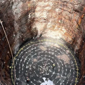
The underground powerhouse is 94m long, 19m wide and 40m deep. The intake shaft has a diameter of 7.5m diameter with an advanced rate by sinking in 2.5m lifts.
The power tunnel is 8.1m by 8.3m inverted D excavated by drilling and blasting in full face. The tailrace tunnel is 6m wide by 10m high excavated by drill and blast with a top heading and bench.
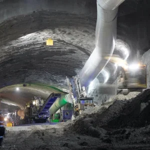
Dell explains that the underground powerhouse was excavated by drilling and blasting with a two-boom jumbo in three drifts and six benches.
“The crown was advanced with a central drift 8m by 8m in full face,” he says. “The support consisted of 100mm of fibre reinforced shotcrete and a pattern of alternating 4m and 6m long, 22mm diameter, CT bolts. The support for each round was installed before the next round was taken.
“All of the tunnels were supported with a minimum of 50mm of fibre reinforced shotcrete and a pattern of CT bolts – mainly 2.4m long but up to 4m and 6m if the rock conditions required it.”
The John Hart Generating Station Replacement project is the Canadian Innovation Project of the Year 2018 for the Tunnelling Association of Canada.